
Tiva Lab 05: Home Control System
Introduction
This lab aims to acquaint learners with the Home Control System using Tiva TM4C LaunchPads. Participants will explore how to effectively use the General Purpose Input/Output (GPIO) configurations and read and write data through pins, thereby controlling various household devices.
Objective
- Understand and implement basic I/O operations.
- Master GPIO configurations.
- Read from input pins and write to output pins to control devices.
Required Reading Materials
- Lesson 07: Create an ARM C Application with Keil μVision MDK-ARM
- Lesson 09: GPIO Ports and Configurations
- Set, Clear, Toggle, and Check Bit Value in C
- Polling Method in Embedded Programming
- Input Signal Edge Detection using Software
- Buzzer
Overview
GPIO (General Purpose Input/Output)
It's an interface standard that allows microcontrollers to connect with other electrical devices. These GPIOs can be set in two primary modes:
- Input Mode
The microcontroller gathers input from other devices, like receiving the status of a button. - Output Mode
The microcontroller sends data to devices, such as instructing an LED to turn on/off.
This lab will guide participants through writing C code to configure GPIO ports, read switch status, and control LEDs.
The GPIO configuration is vital. Post-reset, the software must be initialized, including loading the right configurations described in "Lesson 09: GPIO Ports and Configurations".
You can read the following articles to get more information about LEDs and push-buttons:
- LED & Push-button: EE2449-Lab 01: Introduction to Electrical Circuits
Requirements
Now, a client has asked you to remodel their house. He wants to use an embedded system to control all the lighting systems in the house, including the doorbell. Three types of control systems can be used in a home control:
- A button controls a device: like a doorbell — when the user presses the doorbell button, the system triggers the doorbell to make noise until the button is released.
- A switch controls a group of lights: the lights come on when the user presses the switch. Press again to turn off the lights.
- Multiple switches control a group of lights — for example, a stairwell lighting control system— with switches installed on the first and second floors near the stairs. When the user presses any switch, the light turns on; pressing the same switch again turns it off.
Components Required
 |
Push Button (Switch) | × 4 |
 |
220-ohm Resistor | × 3 |
 |
LED | × 2 |
 |
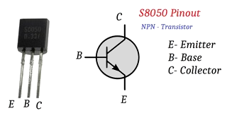
S8050 NPN Transistor | × 1 |
 |
Active Buzzer | × 1 |
 |
Breadboard | × 1 |
Circuit Diagram
The prototype system will use a Tiva board to emulate the three control systems. Details of the circuit can be found in Figure 1 (Simulation Circuit for Home Using TM4C123GXL/TM4C1294) and Figure 1.2 (Circuit Connection on the Breadboard). Also, the pin configurations for different devices are given in Table 1.
EK-TM4C123GXL LaunchPad
 |
 |
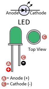 |
Figure 1: The Simulation Circuit for Home Using TM4C123GXL
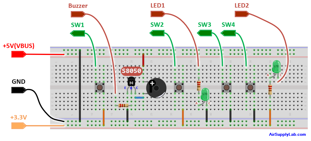
Figure 1.2: The Circuit Connection on the Breadboard
Table 1: Pin Configurations:
| Device | Port.Pin | Signal Type | PCTL | Direction | Drive Mode |
|---|---|---|---|---|---|
EK-TM4C1294XL LaunchPad
 |
|
|
Figure 1: The Simulation Circuit for Home Using TM4C1294XL
Figure 1.2: The Circuit Connection on the Breadboard
Table 1: Pin Configurations:
| Device | Port.Pin | Signal Type | PCTL | Direction | Drive Mode |
|---|---|---|---|---|---|
You must place all the components on the breadboard and use wires to connect the components to the Tiva board. The main functions you have to implement are as follows.
- The SW1 is used to control the buzzer (doorbell).
- The SW2 is used to control LED1.
- The SW3 and SW4 control LED2 that is installed on the stairs.
Procedures
- Make a new folder named "Lab05_HomeControlSystem" inside the "EE3450" folder.
- Launch the Keil μVisio and start a new project. Save the project to the recently created folder named "Lab05_HomeControllSystem".
- Add "MyDefines.h" to the Source Group, then add the Common folder to the "include paths" under the "Options for Target" setting.
Configurations
Implement the Setup_GPIO() function to initialize the GPIO Ports based on the PIN Configuration table.
GPIO Initialization and Configuration
GPIO Initialization Configuration
Next, we need to configure all the GPIO ports and pins that are used in the design.
According to the pin connections, complete the following GPIO configurations for each port. Fills the pin field by the value below:
- 0: Clean the bit
- 1: Set the bit
- x: Do not change the bit
- d: Do not care
For both TM4C123GXL and TM4C1294XL LaunchPads, the Port C [3:0] are used for JTAG/SWD. Therefore, when configuring Port C, use bitwise operators to ensure your new configuration settings do not affect the JTAG/SWD function (PC3 ~ PC0).
Most of the GPIO pins are configured as GPIOs and tri-stated by default (GPIOPCTL = 0, CPIOAFSEL = 0, GPIODIR = 0, GPIOPUR = 0, GPIOPDR = 0, GPIOODR = 0)
- Enable Clock to the GPIO Modules (RCGCGPIO register)
TM4C123G: SYSCTL->RCGCGPIO |= (_PORTs); |= binary = hex
8 4 2 1 8 4 2 1 7 6 5 4 3 2 1 0 bit Port F Port E Port D Port C Port B Port A port 0 0 -
TM4C1294: SYSCTL->RCGCGPIO |= (_PORTs); |= binary = hex
After enabling the clock signal, check the PRGPIO register until the corresponding bit is set to 1.8 4 2 1 8 4 2 1 8 4 2 1 8 4 2 1 15 14 13 12 11 10 9 8 7 6 5 4 3 2 1 0 bit Port Q Port P Port N Port M Port L Port K Port J Port H Port G Port F Port E Port D Port C Port B Port A port 0 - - -
In Assembly:
            LDR     R0, =SYSCTL_PRGPIO_R
Wait4GPIO   LDR     R1, [R0]
            TST     R1, #(__)
            BEQ     Wait4GPIO
In c:
while ( (SYSCTL->PRGPIO & ____ ) != ____ ) {}; - Unlock Port
TM4C123G: PD7 and PF0 are locked after reset.
TM4C1294: PD7 and PE7 are locked after reset
If those pins are used in the design, they must be unlocked first. To unlock the port, 0x4C4F434B must be written into the GPIOLOCK register and uncommitted by setting the GPIOCR register.
8 4 2 1 8 4 2 1 7 6 5 4 3 2 1 0 bit Port Pin 7 Pin 6 Pin 5 Pin 4 - Pin 3 Pin 2 Pin 1 Pin 0 pin Value in Hex Register Value to Register - - = ➤ GPIO ->LOCK = 0x4C4F434B - - = ➤ GPIO ->CR - - = ➤ GPIO ->LOCK = 0x4C4F434B - - = ➤ GPIO ->CR
Convert the above configuration into registers
- GPIO Analog Mode Select
If any pin is used as an Analog signal (check the Signal Type field on table 1), the appropriate bit in AMSEL must be set.
- 0: Digital signal
- 1: Analog signal
8 4 2 1 8 4 2 1 7 6 5 4 3 2 1 0 bit Port Pin 7 Pin 6 Pin 5 Pin 4 - Pin 3 Pin 2 Pin 1 Pin 0 pin Value in Hex Register Value to Register - - = ➤ GPIO ->AMSEL - - = ➤ GPIO ->AMSEL - - = ➤ GPIO ->AMSEL - - = ➤ GPIO ->AMSEL - - = ➤ GPIO ->AMSEL - - = ➤ GPIO ->AMSEL - - = ➤ GPIO ->AMSEL - GPIO Port Control (PCTL)
The PCTL register selects the specific peripheral signal for each GPIO pin in alternate function mode.
- 0: GPIO
- 1~0xF: Check the GPIO Pins and Alternate Function table
8421 8421 8421 8421 8421 8421 8421 8421 31~28 27~24 23~20 19~16 15~12 11~8 7~4 3~0 bit Port Pin 7 Pin 6 Pin 5 Pin 4 - Pin 3 Pin 2 Pin 1 Pin 0 pin Value in Hex Register Value to Register - - = ➤ GPIO ->PCTL - - = ➤ GPIO ->PCTL - - = ➤ GPIO ->PCTL - - = ➤ GPIO ->PCTL - - = ➤ GPIO ->PCTL - - = ➤ GPIO ->PCTL - - = ➤ GPIO ->PCTL - GPIO Alternate Function Select (AFSEL)
Setting a bit in the AFSEL register configures the corresponding GPIO pin to be controlled by PCTL peripheral function.
- 0: General I/O
- 1: Pin connected to the digital function defined in the PCTL register
8 4 2 1 8 4 2 1 7 6 5 4 3 2 1 0 bit Port Pin 7 Pin 6 Pin 5 Pin 4 - Pin 3 Pin 2 Pin 1 Pin 0 pin Value in Hex Register Value to Register - - = ➤ GPIO ->AFSEL - - = ➤ GPIO ->AFSEL - - = ➤ GPIO ->AFSEL - - = ➤ GPIO ->AFSEL - - = ➤ GPIO ->AFSEL - - = ➤ GPIO ->AFSEL - - = ➤ GPIO ->AFSEL - GPIO Pin Direction (DIR)
Set pin direction
- 0: Input pin
- 1: Output pin
8 4 2 1 8 4 2 1 7 6 5 4 3 2 1 0 bit Port Pin 7 Pin 6 Pin 5 Pin 4 - Pin 3 Pin 2 Pin 1 Pin 0 pin Value in Hex Register Value to Register - - = ➤ GPIO ->DIR - - = ➤ GPIO ->DIR - - = ➤ GPIO ->DIR - - = ➤ GPIO ->DIR - - = ➤ GPIO ->DIR - - = ➤ GPIO ->DIR - - = ➤ GPIO ->DIR - Internal Pull-Up Resistor (PUR), Pull-Down Resistor (PDR), and Open-Drain (ODR)
PUR: The pull-up control register
PDR: The pull-down control register
ODR: The open-drain control register
- 0: Disable
- 1: Enable
8 4 2 1 8 4 2 1 7 6 5 4 3 2 1 0 bit Port Pin 7 Pin 6 Pin 5 Pin 4 - Pin 3 Pin 2 Pin 1 Pin 0 pin Value in Hex Register Value to Register - - = ➤ GPIO -> - - = ➤ GPIO -> - - = ➤ GPIO -> - - = ➤ GPIO -> - - = ➤ GPIO -> - - = ➤ GPIO -> - - = ➤ GPIO -> - GPIO Digital Enable
Enables all pins used in the design, including GPIO and alternate-function pins.
- 0: Pin undriven
- 1: Enable pin
8 4 2 1 8 4 2 1 7 6 5 4 3 2 1 0 bit Port Pin 7 Pin 6 Pin 5 Pin 4 - Pin 3 Pin 2 Pin 1 Pin 0 pin Value in Hex Register Value to Register - - = ➤ GPIO ->DEN - - = ➤ GPIO ->DEN - - = ➤ GPIO ->DEN - - = ➤ GPIO ->DEN - - = ➤ GPIO ->DEN - - = ➤ GPIO ->DEN - - = ➤ GPIO ->DEN
Example Source Code
Lab Template Firmware Source Code
This section provides the template firmware source code for the TM4C123G and TM4C1294 platforms used in these laboratory exercises. Explanatory notes are included to help readers understand the purpose and operation of each major part of the program.
The provided code is intended as a reference starting point and may be copied into the project as needed. Since the template is not a final, complete program, it should be reviewed and modified to meet the requirements of each experiment. Unnecessary statements may be commented out, and appropriate comments should be added to clearly document the program structure and implementation details.
EK-TM4C123GXL LaunchPad - main.c
#include <stdio.h>
#include <stdlib.h>
#include <stdint.h>
#include <stdbool.h>

#include "TM4C123GH6PM.h"
#include "MyDefines.h"

void Doorbell(void);
void RoomLightingControl(void);
void StairwallLightingControl(void);

void DelayMs(int ms);   // Software Delay Function
void Setup_GPIO(void);

int main()
{
    // Place your initialization/startup code here (e.g. Setup_GPIO() )
    Setup_GPIO();

    // Turn off LED2 here
    GPIOx->DATA _________;

    while (1) {
        Doorbell();
        RoomLightingControl();
        StairwallLightingControl();

        DelayMs(20);
    }
}
//------------------------------------------------------------------------------
void Doorbell()
{
    // Place your application code here

}
//------------------------------------------------------------------------------
void RoomLightingControl()
{
    static bool preSw2 = ____;
    bool        curSw2;

    // Place your application code here

}
//------------------------------------------------------------------------------
void StairwallLightingControl()
{
    static bool preSw3 = ____;
    bool        curSw3;
    static bool preSw4 = ____;
    bool        curSw4;

    // Place your application code here

}
//------------------------------------------------------------------------------
/*
Device      Port.Pins       DIR     DriveMode
SW1
SW2
SW3
SW4
Buzzer
LED1
LED2

Port ____
*/

void Setup_GPIO()
{
    // Configure GPIOs
    // 1. Enable Clock to the GPIO Modules (SYSCTL->RCGCGPIO |= (_PORTs);)
    SYSCTL->RCGCGPIO |= (__);
    // allow time for clock to stabilize (SYSCTL->PRGPIO & (_PORTs))
    while ((SYSCTL->PRGPIO & (__)) != (__)) {};
    // 2. Unlock GPIO only PD7, PF0 on TM4C123G; PD7, PE7 on TM4C1294 (GPIOx->LOCK = 0x4C4F434B; and GPIOx->CR = _PINs;)
    //GPIOF->LOCK = 0x4C4F434B;   // Unlock for GPIOF
    //GPIOF->CR |= _PIN0;         // Commit for PIN0
    // 3. Set Analog Mode Select bits for each Port (GPIOx->AMSEL = _PINs;)
    // 4. Set Port Control Register for each Port (GPIOx->PCTL = PMCn << _PTCL_PINn, check the PCTL table)
    // 5. Set Alternate Function Select bits for each Port (GPIOx->AFSEL = _PINs;)
    // 6. Set the output pins for each port only (Direction of the Pins: GPIOx->DIR = _PINs;)

    // 7. Set PUR bits (internal Pull-Up Resistor), PDR (Pull-Down Resistor), ODR (Open Drain) for each Port

    // 8. Set Digital ENable register on all digital port.pins (GPIOx->DEN = _PINs;)

}
//------------------------------------------------------------------------------
// Delay ms milliseconds (4167:50MHz TM4C123G CPU, 1605:16MHz TM4C123G CPU Clock)
void DelayMs(int ms)
{
    volatile int i, j;
    for (i = 0; i < ms; i++)
        for (j = 0; j < 4167; j++) {} // Do nothing for 1ms
}
//------------------------------------------------------------------------------
EK-TM4C1294XL LaunchPad - main.c
#include <stdio.h>
#include <stdlib.h>
#include <stdint.h>
#include <stdbool.h>

#include "TM4C1294NCPDT.h"
#include "MyDefines.h"

void Doorbell(void);
void RoomLightingControl(void);
void StairwallLightingControl(void);

void DelayMs(int ms);   // Software Delay Function
void Setup_GPIO(void);

int main()
{
    // Place your initialization/startup code here (e.g. Setup_GPIO() )
    Setup_GPIO();

    // Turn off LED2 here
    GPIOx->DATA _________;

    while (1) {
        Doorbell();
        RoomLightingControl();
        StairwallLightingControl();

        DelayMs(20);
    }
}
//------------------------------------------------------------------------------
void Doorbell()
{
    // Place your application code here

}
//------------------------------------------------------------------------------
void RoomLightingControl()
{
    static bool preSw2 = ____;
    bool        curSw2;

    // Place your application code here

}
//------------------------------------------------------------------------------
void StairwallLightingControl()
{
    static bool preSw3 = ____;
    bool        curSw3;
    static bool preSw4 = ____;
    bool        curSw4;

    // Place your application code here

}
//------------------------------------------------------------------------------
/*
Device      Port.Pins       DIR     DriveMode
SW1
SW2
SW3
SW4
Buzzer
LED1
LED2

Port ____
*/

void Setup_GPIO()
{
    // Configure GPIOs
    // 1. Enable Clock to the GPIO Modules (SYSCTL->RCGCGPIO |= (_PORTs);)
    SYSCTL->RCGCGPIO |= (__);
    // allow time for clock to stabilize (SYSCTL->PRGPIO & (_PORTs))
    while ((SYSCTL->PRGPIO & (__)) != (__)) {};
    // 2. Unlock GPIO only PD7, PF0 on TM4C123G; PD7, PE7 on TM4C1294 (GPIOx->LOCK = 0x4C4F434B; and GPIOx->CR = _PINs;)
    // 3. Set Analog Mode Select bits for each Port (GPIOx->AMSEL = _PINs;)
    // 4. Set Port Control Register for each Port (GPIOx->PCTL = PMCn << _PTCL_PINn, check the PCTL table)
    // 5. Set Alternate Function Select bits for each Port (GPIOx->AFSEL = _PINs;)
    // 6. Set the output pins for each port only (Direction of the Pins: GPIOx->DIR = _PINs;)

    // 7. Set PUR bits (internal Pull-Up Resistor), PDR (Pull-Down Resistor), ODR (Open Drain) for each Port

    // 8. Set Digital ENable register on all digital port.pins (GPIOx->DEN = _PINs;)

}
//------------------------------------------------------------------------------
// Delay ms milliseconds (1605: 16MHz TM4C1294 CPU Clock)
void DelayMs(int ms)
{
    volatile int i, j;
    for (i = 0; i < ms; i++)
        for (j = 0; j < 1605; j++) {}   // // Do nothing for 1ms
}
//------------------------------------------------------------------------------
Lab Experiments
Exp #2.1: Doorbell Control
The doorbell control circuit is very simple. When you prod the button, the circuit will be connected, and you will hear a buzzing noise. The electrical circuit for the doorbell is shown as the following Figure 3:

Figure 3: The Electrical Circuit for Doorbell

Figure 4: The Simulation Circuit for Doorbell
We use a microcontroller to implement the doorbell circuit. From Figure 3, we can easily understand that the doorbell is triggered only when a user presses the button, otherwise, the doorbell should be inactive. Then we convert the circuit behaviors to a flowchart, as shown in Figure 5.

Figure 5: The Flowchart for Doorbell Controller.
Implement the flowchart in the Doorbell() function. Build and download the code to the Tiva board, and test it.
Exp #2.2: Room Lighting Control
Most rooms in a house will have one or more wall switches used to control lighting fixtures or electrical outlets. There have only three kinds of wall switches that are used to control light fixtures: simple single-pole (ON/OFF) switches, three-way switches, and four-way switches. A Single-Pole switch is one that just turns the light ON or OFF from one wall location.

Figure 6: Simple Room Light Control


Figure 7: A Single-Pole Switch Using on Light Control

Figure 8: The Electrical Circuit for Room Light Control

Figure 9: The Simulation Circuit for Room Light Control
A single-pole switch has two positions: OFF and ON. When you toggle the lever to the ON position, the switch gate snaps closed, which allows current to flow through the light. The switch will remain in the ON position until the lever is flipped to the OFF position, which opens the gateway up and interrupts the flow of power to the light. The electrical circuit is shown in Figure 8.
The switches we used in the circuit are momentary pushbutton switches. They are non-latching switches and change the state of the electrical circuit only while the switch is physically actuated. In other words, a momentary switch allows electricity to flow between its two contacts while the button is depressed. Upon releasing the button, the circuit is broken.
Therefore, to implement a room light controller, the microcontroller needs to retain the state of the light or switch, and when the user presses the button, it will then change the state of the light or switch. In the code, the current state needs to be saved as a variable.
You may think of using the same flowchart that was used in the previous experiment to control the light. In Figure 5, when the system detects the button pressed, it will turn on the light. The system will continue to check the state of the switch, and once the user releases the button, the system will detect that the switch is off and turn OFF the light.
However, the goal for today is to keep the light turned ON until the button is pressed again. By using the technique from the previous experiment, customers will have to hold on to the button to turn ON the light and can only release it when the light is not needed.
Two solutions can be used in this case:
- Finite State Machine (based on behavior state)
- Software Edge Detection (based on electrical timing)
Software Edge Detection
Software Edge Detection
Let us analyze the system's behavior according to the timing sequence.
In the circuit shown in Figure 9, SW2 is connected to the microcontroller's input pin as a positive-logic input. This means that when the user presses the switch, the input pin is connected to the power supply, so its logic value is 1. If the user releases the switch, the switch disconnects; the input pin connects to ground through the (internal) pull-down resistor, and the input pin's logic value becomes 0. The timing diagram for the SW2 is shown in Figure 11.
From the Moore state diagram (Figure 10), we can observe that the LED output changes each time the user presses the switch. If the user continues to hold or release the switch, the LED will not change. In the timing diagram, you can see that when the user presses SW2, the logic value of the input pin changes from 0 to 1; the point at which this change occurs is called the rising edge. We found that the LED changes only on the falling edge of the input pin. Hence, the microcontroller just needs to detect the rising edge on the input pin and then change the output value.
A simple if statement method is convenient for implementing software edge detection. In the code, you have to create two local variables:
- One is a static local Boolean variable (ex. static bool preSW2) that holds the last state value. This variable is also assigned an initial value equal to the logic value of the input pin when the switch is inactive.
- Another local Boolean variable without an initial value (ex. bool curSW2) is used to save the current state of the input pin.
The following steps show how to detect the falling edge:
- Read the current state value of the input pin that connects to the SW2 and save that value to the curSW2 variable.
- Check the previous and current state variables:
If the previous state preSW2 is logic 0 (which means the SW2 has been released before) and the current state curSW2 is logic 1 (just pressing the SW2), it means that a rising edge occurred on the pin that is connected to the SW2, and then changes the LED state - Stores the current state value to the previous state variable (preSW2 = curSW2).
BEGIN

    READ SW2_CURRENT_STATE INTO curSW2

    IF preSW2 = LOW AND curSW2 = HIGH THEN
        TOGGLE LED
    ENDIF

    preSW2 ← curSW2

END
Comment out all the previous code in the RoomLightingControl() function and implement the software edge detection (simple if statement method). Build and download the code to the Tiva board, then show the result to the instructor.
Exp #2.3: Stairwell Lighting Control
Next, implement a control switch commonly used in stairwells, as shown in Figure 12.

Figure 12: The Light Control System at the Stairwells
The stairwell lights are controlled by switches that are installed on each floor. When you want to go up/down the stairs, just press the switch to turn on the wall lights. After reaching the target floor, simply press the switch on the floor you're on to turn off the lights.
Now, you have to design a system to support the stairwell light. Two switches control one LED, so you can turn it on with one switch and turn it off with the other. The code should be similar to the previous experiment, but add one more switch to toggle the LED.
After resetting, LED2 should be turned off. If LED2 is on, you have to turn it off after calling the Setup_GPIO() function before entering the infinite while loop.
Software Edge Detection on Both Switches
You can use the toggle function with edge detection to control the light. The pseudocode is as follows:
Using Software Edge Detection
BEGIN

    READ SW3_CURRENT_STATE
    READ SW4_CURRENT_STATE

    IF SW3_PREVIOUS_STATE = HIGH AND SW3_CURRENT_STATE = LOW THEN
        TOGGLE LED2
    ENDIF

    IF SW4_PREVIOUS_STATE = HIGH AND SW4_CURRENT_STATE = LOW THEN
        TOGGLE LED2
    ENDIF

    SW3_PREVIOUS_STATE ← SW3_CURRENT_STATE
    SW4_PREVIOUS_STATE ← SW4_CURRENT_STATE

END