Lesson 08: Add ezTiva Library to Your Project
The ezTiva Library is a Keil v5.x library for TI Tiva LaunchPad — TM4C123G and TM4C1294 microcontrollers.
Add ezTiva LIB to Your Project
1. EZ-Tiva Library
- Download ezTiva Library
- Current Version:
- Previous Version:
V1.2.8
- Current Version:
- Extract the zip file.
- Copy the ezTivaLib folder to your project home folder, such as the EE3450 folder.
Version History:
- 1.2.10 (2026/04/08)
- + Added ezAsyncDelayUs() and ezAsyncDelay() for non‑blocking delay with callback
- + Added class‑style timer system (ezTimerClass) with Timer5A/4A support
- + Added ezDelay_Done() for non-blocking delay DONE flag
- # Modified ezDelay() and ezDelayUs() to use new Timer5A 32‑bit delay engine
- # Improved delay accuracy across different system clock frequencies
- # Updated codebase to support both TM4C123GH6PM and TM4C1294NCPDT
- # Modified ON_3_0 to _ON_PIN_3_0
- - Removed old timer_waitMillis() and timer_waitMicros() implementations
- 1.2.8 (2021/04/14)
- Add ezDelay() and ezDelayUs() function
- For LCD, add ezLCD_PutChar()
- 1.2.6 (2021/03/25)
- Fixed the LCD driver compatibility issue.
- 1.2.5 (2020/10/28)
- Support updating SystemCoreClock variable after change the system clock frequency.
- Change the library filename to ez123G.lib and ez1294.lib.
- 1.2.4 (2020/10/13)
- Using Compiler V6 to rebuild the libraries for both boards.
- Add a delay to fix compatibility issues for some LCD modules.
- 1.2.3 (2018/02/20)
- Using Compiler V5.06 update 5 (build 528) to rebuild the libraries for both boards.
- 1.2.2 (2017/12/02)
- Add more configurations for system clock setting
- Fixed the timer_waitMillis() function error in different system clock
2. Add ezTiva LIB
- In the Project tab, right-click on "Source Group 1" to open "Add Files..." window.
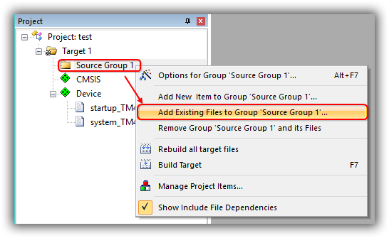
- In the "Add Files.." window, change the "Files of type" to "Library file (*.lib)"
Click on Add and then click on Close to return to the main menu.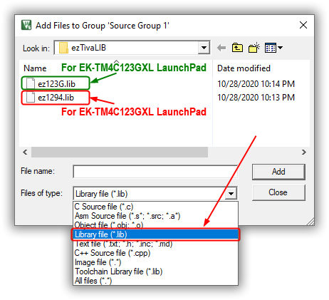
3. Increase Stack and Heap
The stack is used for static memory allocation and Heap for dynamic memory allocation, both stored in the computer's RAM.
In C, when a function declares a local variable, it is "pushed" onto the stack. All the local variables will be deleted when the function exits. Or when a function or a method calls another function, sometimes the parameters and return address will be stored onto the stack.
When you use malloc() or calloc() to allocate dynamic memory space, it will be allocated on the heap. Once you have allocated memory on the heap, you are responsible for using free() to deallocate that memory once you don't need it anymore.
Change the memory size for stack and heap
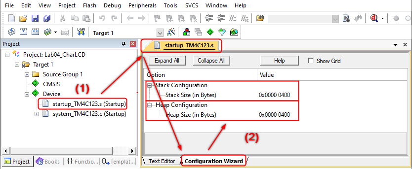
The default memory size for the stack is 0x200 (512) bytes, 0x0 (0) bytes for the heap. Therefore, we need to modify the memory size for both.
- In the Project tab under Device, double-click on "startup_TM4xxx.s (Startup)" to open it up.
- Select its "Configuration Wizard" tab. Change the Stack Size to 0x400 bytes (1024 bytes) and Heap Size is to 0x400 bytes (1024 bytes)
4. Add ezTivaLIB to the Include Path
Next, you need to add the ezTivaLIB folder to the Options for Target ➤ C/C++ tab ➤ Include Paths.
- Select Options for Target (Alt+F7) from the Project menu, or click
 button to open the Options window.
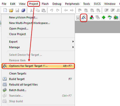
- Change to C/C++ tab. Click the button that is in the Include Paths field to setup a folder. In the Folder Setup window, click the New (Insert) button to add the ezTivaLIB folder to the Include Paths.
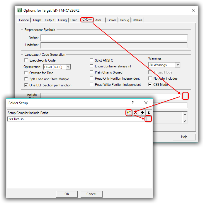
- Click OK to close the Options window.
ezTiva LIB API
System Frequency
Using System Frequency Configuration Functions
for TM4C123G and TM4C1294 Microcontrollers
The ezSysClock module provides a set of simple, high‑level system clock configuration functions for both TM4C123GH6PM and TM4C1294NCPDT microcontrollers. Each function configures the CPU core frequency, PLL, and clock dividers to a predefined and stable operating frequency.
The clock setup functions in this module are hardware‑specific and selected automatically at compile‑time using #if defined(TM4C123GH6PM) or #if defined(TM4C1294NCPDT).
1. System Clock Functions for TM4C123G
The following functions are available when the device is defined as TM4C123GH6PM:
Setup_123G_80MHz();Setup_123G_50MHz();Setup_123G_40MHz();Setup_123G_25MHz();Setup_123G_20MHz();Setup_123G_16MHz();Setup_123G_8MHz();- Configures system clock via RCC/RCC2 registers
- Uses PLL (400 MHz VCO) with divider for final frequency
- SystemCoreClock is updated internally
2. System Clock Functions for TM4C1294
The following functions are available when the device is defined as TM4C1294NCPDT:
Setup_1294_120MHz();Setup_1294_96MHz();Setup_1294_80MHz();Setup_1294_60MHz();Setup_1294_48MHz();Setup_1294_40MHz();Setup_1294_32MHz();Setup_1294_30MHz();Setup_1294_24MHz();Setup_1294_20MHz();Setup_1294_16MHz();Setup_1294_12MHz();Setup_1294_6MHz();- Configures MOSC, PLL, memory timing, and divisors via RSCLKCFG and PLLFREQ registers
- Optimizes flash wait states based on selected frequency
- SystemCoreClock updated for correct timing operations
3. Typical Usage
To change system frequency, simply call one of the predefined functions at the beginning of main(). The clock system is fully configured, and all dependent modules (Timers, UART, SysTick, PWM, etc.) will use the updated SystemCoreClock value.
#include "ezSysClock.h"
#include "ezDelay.h"

int main(void)
{
    // -----------------------------
    // Select system frequency
    // -----------------------------

#if defined(TM4C123GH6PM)
    Setup_123G_80MHz();     // Set TM4C123 to 80 MHz
#elif defined(TM4C1294NCPDT)
    Setup_1294_120MHz();    // Set TM4C1294 to 120 MHz
#endif

    Setup_GPIO();

    // Use delay functions (use updated SystemCoreClock)
    ezDelay(500);           // 500 ms delay
    ezDelayUs(50);          // 50 us delay

    while (1) {
        // your main loop code here
    }
}
4. Notes & Best Practices
- Call system frequency setup before initializing peripherals.
- All delay functions and timing‑dependent modules rely on SystemCoreClock.
- Changing system clock after peripherals are initialized may require reconfiguration.
- Always match system frequency selection to board power/oscillator specifications.
These functions simplify working with the TM4C clock system by providing ready‑to‑use, stable configurations without manually manipulating PLL or RCC registers.
Delay Function
Using ezDelay — Blocking & Non‑Blocking Delay Functions
The ezDelay library provides two types of delay mechanisms for TM4C123/TM4C129 microcontrollers:
- Blocking delay using Timer5A
- Non‑blocking delay using Timer4A + interrupt
This document explains how each delay function works, how to use them, and how to check the status of a non‑blocking delay using ezDelay_Done(). You may optionally use a callback function or set callback to NULL if no callback is needed.
1. Blocking Delay Functions (Timer5A)
Blocking delays stop the CPU until the requested delay time is finished.
void ezDelay (uint32_t ms);void ezDelayUs(uint32_t us);- ezDelay(ms) — Delay in milliseconds
- ezDelayUs(us) — Delay in microseconds
These functions are simple and accurate, but the CPU cannot run other tasks until the delay completes.
2. Non‑Blocking Delay Functions (Timer4A + Interrupt)
Non‑blocking delay allows the program to continue running while the timer counts in the background.
void ezAsyncDelayUs(uint32_t us, void (*callback_addr)(void));void ezAsyncDelay (uint32_t ms, void (*callback_addr)(void));- The delay runs asynchronously (does NOT block CPU)
- callback_addr is called when the delay finishes
- You may pass
NULLif no callback is needed
Internally, the system uses Timer4A and its interrupt to trigger the completion event.
3. Checking Delay Completion: ezDelay_Done()
You can check whether a non‑blocking delay has finished:
bool ezDelay_Done(void);- Returns true when the async delay has completed
- Returns false while the delay is still running
This is useful when you do not want to use a callback function.
4. Example C Code
Below is a simple demo showing how to use all delay modes.
#include "ezDelay.h"
#include "TM4C1294NCPDT.h"   // or TM4C123GH6PM.h
#include "MyDefines.h"

// ---------------------------------------------------------
// Optional callback function for async delay
// ---------------------------------------------------------
void BlinkLED(void)
{
    GPION_AHB->DATA ^= _PIN0;   // Toggle LED
}

// ---------------------------------------------------------
// Main demo program
// ---------------------------------------------------------
int main(void)
{
    Setup_GPIO();

    // 1. Blocking delay example
    ezDelay(500);      // 500 ms blocking delay
    ezDelayUs(50);     // 50 us blocking delay

    // 2. Non-blocking delay without callback
    ezAsyncDelayUs(200000, NULL);   // 200 ms async delay (no callback)
    while (!ezDelay_Done());

    while (1) {
        // Check async delay completion
        if (ezDelay_Done()) {
            // Restart another async delay
            // 3. Non-blocking delay using callback
            ezAsyncDelay(1000, BlinkLED);   // Toggle LED after 1 sec
        }

        // CPU can do other tasks here
    }
}
Summary
- Use ezDelay() for simple blocking delays
- Use ezAsyncDelay() for background timers
- Provide a callback or pass
NULL - Use ezDelay_Done() to poll asynchronous status
This delay system is designed for real‑time embedded applications on TM4C microcontrollers, allowing high precision and flexible scheduling without blocking CPU resources.
Do not use Timer5 (T5CCP0) or Timer4 (T4CCP0) in your project; they are used for the hardware timer delay functions — ezDelay()/ezDelayUs() and ezAsyncDelay()/ezAsyncDelayUs().
Character LCD APIs
The Character LCD APIs enable simple use of one-, two-, or four-line LCD modules that use the Hitachi 44780 standard 4-bit interface. The APIs also implement horizontal and vertical bar graphs, or you can create and display your own custom characters.
LCD Connections
This section describes the various input and output connections available for the Character LCD.
Data Pins
Data transfer between the Tiva LaunchPad and the Character LCD module will occur via the 4-bit interface. The D4 ~ D7 (Pin 11 ~ 14) of the LCD module must be connected to start on the first physical pin of a port on the Tiva LaunchPad; it may not span ports. That is, the D4 pin could theoretically be Port D pin 0 or Port E pin 0. Forcing the LCD data port to be at pin 0 can improve efficiency by reducing the number of shifts required to align data for a write.
Control Pins
The RS (data/command pin), R/W (read/write pin), and EN (enable pin) pins can be connected to any pins on the Tiva LaunchPad.
All the GPIO pins on the Tiva LaunchPad that are connected to the LCD module are output pins.
The following is an example to connect the
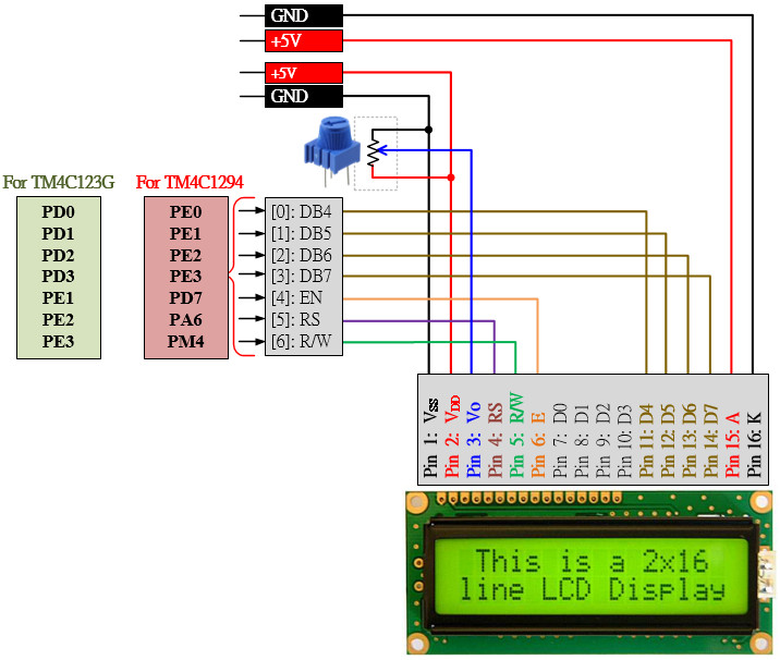
Figure: The Connections between the LCD Module and Tiva LaunchPad.
Before using the LCD module, the LCD object must be created and assigned to the port.pins based on the circuit connection. The example code as follows:
    PEZOBJ_LCD  lcd;    // LCD Object

    lcd = ezLCD_Create();                                               // Creating a new Hardware LCD Object
    ezLCD_Connect_DataPort(lcd, _PORTD, _ON_PIN_3_0);                   // Connecting DATA port on PortD[3:0]
    ezLCD_Connect_ENPin(lcd, _PORTE, _PIN1);                            // Connecting EN pin on PortE[1]
    ezLCD_Connect_RSPin(lcd, _PORTE, _PIN2);                            // Connecting RS pin on PortE[2]
    ezLCD_Connect_RWPin(lcd, _PORTE, _PIN3);                            // Connecting RW pin on PortE[3]

    ezLCD_Start(lcd);                                                   // Starting lcd object
Line 1: Declare an LCD object
Line 3: After initializing the GPIO ports, create a new hardware LCD object and then assign it to the lcd object pointer.
Line 4: Connect data pins (D4 ~ D7) to Port D pin 0 ~ pin 3.
Line 5: Connect the EN (enable) pin to Port E pin 1.
Line 6: Connect the RS (data/command) pin to Port E pin2.
Line 7: Connect the RW (read/write) pin to Port E pin 3.
Application Programming Interface (API)
void ezLCD_Start(PEZOBJ_LCD lcd)
| Description: |
This function will start up the LCD object and initialize the LCD hardware module as follows:
|
| Parameters: | PEZOBJ_LCD lcd: LCD object |
| Return Value: | None |
| Side Effects: | None |
void ezLCD_ClearDisplay(PEZOBJ_LCD lcd)
| Description: | Clears the contents of the LCD screen and resets the cursor location to be row and column zero. |
| Parameters: | PEZOBJ_LCD lcd: LCD object |
| Return Value: | None |
| Side Effects: | None |
void ezLCD_Position(PEZOBJ_LCD lcd, uint8_t row, uint8_t column)
| Description: | Move the cursor to the location specified by the argument row and column. |
| Parameters: | PEZOBJ_LCD lcd: LCD object. uint8_t row: The row number at which to position the cursor. uiny8_t column: The column number at which to position the cursor. |
| Return Value: | None |
| Side Effects: | None |
void ezLCD_PrintString(PEZOBJ_LCD lcd, char const str[])
| Description: | Writes a null-terminated string of characters to the LCD screen beginning at the current cursor location. |
| Parameters: | PEZOBJ_LCD lcd: LCD object. char const str[]: Null-terminated array of ASCII characters to be displayed on the LCD screen. |
| Return Value: | None |
| Side Effects: | None |
void ezLCD_PrintInt8(PEZOBJ_LCD lcd, uint8_t value)
| Description: | Prints a two-ASCII-character representation of the 8-bit value to the Character LCD screen at the current cursor location. |
| Parameters: | PEZOBJ_LCD lcd: LCD object. uint8_t value: The 8-bit value to be printed in hexadecimal ASCII characters. |
| Return Value: | None |
| Side Effects: | None |
void ezLCD_PrintInt16(PEZOBJ_LCD lcd, uint16_t value)
| Description: | Prints a four-ASCII-character representation of the 16-bit value to the Character LCD screen at the current cursor location. |
| Parameters: | PEZOBJ_LCD lcd: LCD object. uint16_t value: The 16-bit value to be printed in hexadecimal ASCII characters. |
| Return Value: | None |
| Side Effects: | None |
void ezLCD_PrintInt32(PEZOBJ_LCD lcd, uint32_t value)
| Description: | Prints an eight-ASCII-character representation of the 32-bit value to the Character LCD screen at the current cursor location. |
| Parameters: | PEZOBJ_LCD lcd: LCD object. uint32_t value: The 32-bit value to be printed in hexadecimal ASCII characters. |
| Return Value: | None |
| Side Effects: | None |
void ezLCD_Number(PEZOBJ_LCD lcd, uint16_t value)
| Description: | Prints the decimal value of a 16-bit value as left-justified ASCII characters. |
| Parameters: | PEZOBJ_LCD lcd: LCD object uint16_t value: The 16-bit value to be printed in ASCII characters as a decimal number |
| Return Value: | None |
| Side Effects: | None |
void ezLCD_Print32Number(PEZOBJ_LCD lcd, uint32_t value)
| Description: | Prints the decimal value of a 32-bit value as left-justified ASCII characters. |
| Parameters: | PEZOBJ_LCD lcd: LCD object. uint32_t value: The 32-bit value to be printed in ASCII characters as a decimal number |
| Return Value: | None |
| Side Effects: | None |
Example Code
EK-TM4C123GXL LaunchPad
#include <stdio.h>
#include <stdlib.h>
#include <stdbool.h>
#include <stdint.h>

#include "TM4C123GH6PM.h"
#include "MyDefines.h"
#include "ez123G.h"

char str[100];

void Setup_GPIO();

int main(void)
{
    PEZOBJ_LCD  lcd;    // LCD Object
    uint16_t    i = 0;

    Setup_GPIO();       // GPIO Configuration

    lcd = ezLCD_Create();                           // Creating a new Hardware LCD Object
    ezLCD_Connect_DataPort(lcd, _PORTD, _ON_PIN_3_0);// Connecting DATA port on PortD[3:0]
    ezLCD_Connect_ENPin(lcd, _PORTE, _PIN1);        // Connecting EN pin on PortE[1]
    ezLCD_Connect_RSPin(lcd, _PORTE, _PIN2);        // Connecting RS pin on PortE[2]
    ezLCD_Connect_RWPin(lcd, _PORTE, _PIN3);        // Connecting RW pin on PortE[3]

    ezLCD_Start(lcd);                               // Starting lcd object
    ezLCD_LoadVerticalBargraphFonts(lcd);           // Load vertical bargraph fonts

    ezLCD_ClearDisplay(lcd);                        // Clear LCD display
    ezLCD_PrintString(lcd, "HELLO");                // Display string on LCD screen
    ezLCD_Position(lcd, 1,0);                       // Set dispplay position at [1,0] (raw 1. col 0)
    ezLCD_PrintString(lcd, "TI Tiva 123G");         // Display string on LCD screen

    while (1){
        sprintf(str,"i = %d  ", i);
        ezLCD_Position(lcd, 0, 6);
        ezLCD_PrintString(lcd, str);

        ezLCD_DrawVerticalBG(lcd, 1, 15, 2, i%16);  // Draw a vertical bar at (1,6), maximum 2 characters, bar number is 0~15
        i++;
        timer_waitMillis(100);                      // Hardware timer delay for 100 ms
    }
}

void Setup_GPIO()
{
    // GPIO Initialization and Configuration
    // 1. Enable Clock to the GPIO Modules (SYSCTL->RCGCGPIO |= (_PORTs);)
    SYSCTL->RCGCGPIO |= (_PORTs); |= (__);
    // allow time for clock to stabilize (SYSCTL->PRGPIO & (_PORTs))
    while ((SYSCTL->PRGPIO & (__)) != (__)) {};
    // 2. Unlock GPIO only PD7, PF0 on TM4C123G; PD7 on TM4C1294 (GPIOx->LOCK = 0x4C4F434B; and GPIOx->CR = _PINs;)
    // 3. Set Analog Mode Select bits for each Port (GPIOx->AMSEL = _PINs;)
    // 4. Set Port Control Register for each Port (GPIOx->PCTL = PMCn << _PTCL_PINn, check the PCTL table)
    // 5. Set Alternate Function Select bits for each Port (GPIOx->AFSEL = _PINs;)
    // 6. Set Output pins for each Port (Direction of the Pins: GPIOx->DIR = _PINs;)

    // 7. Set PUR bits (internal Pull-Up Resistor), PDR (Pull-Down Resistor), ODR (Open Drain) for each Port
    // 8. Set Digital ENable register on all GPIO pins (GPIOx->DEN = _PINs;)

}
EK-TM4C1294XL LaunchPad
#include <stdio.h>
#include <stdlib.h>
#include <stdbool.h>
#include <stdint.h>

#include "TM4C1294NCPDT.h"
#include "MyDefines.h"
#include "ez1294.h"

char str[100];
void Setup_GPIO();

int main(void)
{
    PEZOBJ_LCD  lcd;
    uint16_t    i = 0;

    Setup_GPIO();

    lcd = ezLCD_Create();                           // Creating a new Hardware LCD Object
    ezLCD_Connect_DataPort(lcd, _PORTE, _ON_PIN_3_0);// Connecting DATA port on PortE[3:0]
    ezLCD_Connect_ENPin(lcd, _PORTD, _PIN7);        // Connecting EN pin on PortD[7]
    ezLCD_Connect_RSPin(lcd, _PORTA, _PIN6);        // Connecting RS pin on PortA[6]
    ezLCD_Connect_RWPin(lcd, _PORTM, _PIN4);        // Connecting RW pin on PortM[4]

    ezLCD_Start(lcd);                               // Starting lcd object
    ezLCD_LoadVerticalBargraphFonts(lcd);           // Load vertical bargraph fonts

    ezLCD_ClearDisplay(lcd);                        // Clear LCD display
    ezLCD_PrintString(lcd, "HELLO");                // Display string on LCD screen
    ezLCD_Position(lcd, 1,0);                       // Set dispplay position at [1,0] (raw 1. col 0)
    ezLCD_PrintString(lcd, "TI Tiva 1294");         // Display string on LCD screen

    while (1){
        sprintf(str,"i = %d  ", i);
        ezLCD_Position(lcd, 0, 6);
        ezLCD_PrintString(lcd, str);

        ezLCD_DrawVerticalBG(lcd, 1, 15, 2, i%16);  // Draw a vertical bar at (1,6), maximum 2 characters, bar number is 0~15
        i++;
        timer_waitMillis(100);                      // Hardware timer delay for 100 ms
    }
}

void Setup_GPIO()
{
    // GPIO Initialization and Configuration
    // 1. Enable Clock to the GPIO Modules (SYSCTL->RCGCGPIO |= (_PORTs);)
    SYSCTL->RCGCGPIO |= (_PORTs); |= (__);
    // allow time for clock to stabilize (SYSCTL->PRGPIO & (_PORTs))
    while ((SYSCTL->PRGPIO & (__)) != (__)) {};
    // 2. Unlock GPIO only PD7, PF0 on TM4C123G; PD7 on TM4C1294 (GPIOx->LOCK = 0x4C4F434B; and GPIOx->CR = _PINs;)
    GPIOD_AHB->LOCK = 0x4C4F434B;
    while ((GPIOD_AHB->LOCK & 0x01) == 0x01); // Unlocked when reading the GPIOx->LOCK = 0x4C4F434B; ==0x00
    *(((char*)GPIOD_AHB)+0x524) = 0xFF;

    // 3. Set Analog Mode Select bits for each Port (GPIOx->AMSEL = _PINs;  0=digital, 1=analog)
    // 4. Set Port Control Register for each Port (GPIOx->PCTL = PMCn << _PTCL_PINn, check the PCTL table)
    // 5. Set Alternate Function Select bits for each Port (GPIOx->AFSEL = _PINs;  0=regular I/O, 1=PCTL peripheral)
    // 6. Set Output pins for each Port (Direction of the Pins: GPIOx->DIR = _PINs;  0=input, 1=output)

    // 7. Set PUR bits (internal Pull-Up Resistor), PDR (Pull-Down Resistor), ODR (Open Drain) for each Port
    // 8. Set Digital ENable register on all GPIO pins (GPIOx->DEN = _PINs;)

}