FPGA Lab 01: Switches, LEDs, and Multiplexers
Objectives
The purpose of this exercise is to learn how to connect simple input and output devices to an FPGA chip and implement a circuit that uses these devices. We will use the switches on the DE10-Lite board as inputs to the circuit. We will use light-emitting diodes (LEDs) as output devices.
Required Reading Material
- Textbook: Digital Design: with An Introduction to the Verilog HDL, VHDL, and SystemVerilog, 6th edition, Mano and Ciletti, ISBN-13: 978-0-13-454989-7
Ch 4.5 - Lesson 01: Create a New FPGA Project using Quartus Prime Standard
- Lesson KB 02: Intel DE10-Lite Board
Background Information
DE10-Lite FPGA Board Switches and LEDs
The Intel DE10-Lite FPGA board has ten switches and LEDs. The connections between the switches and LEDs are shown in the following Figures:

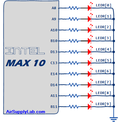
Figure 1: The Connections of Switches and LEDs on the DE10-Lite FPGA Board
Multiplexers (MUX)
In digital circuits, a multiplexer (or MUX) is a device that selects one of several digital input signals and forwards the selected input into a single line. A multiplexer of 2n inputs has n select lines, which are used to select which input line to send to the output.
- A 2n-to-1 multiplexer sends one of the 2n input lines to a single output line.
- A multiplexer has two sets of inputs:
- 2n data input lines
- n select lines to pick one of the 2n data inputs
- The mux output is a single bit, which is one of the 2n data inputs.
2-to-1 1-bit MUX
Figure 2 (b) shows a sum-of-products circuit that implements a 2-to-1 multiplexer with a select input s. If s = 0, the output of the multiplexer (out) is equal to the input in0; if s = 1, the output is equal to in1. Part (a) of the figure gives a function table for this multiplexer, and part (c) shows its circuit symbol.
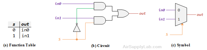
Figure 2: A 2-to-1 Multiplexer
2-to-1 4-bit MUX
Write a Verilog module with four assignment statements like the one shown above to describe the circuit given in Figure 3 (a). This circuit has two four-bit inputs, In0 and In1, and produces the four-bit output Out. If S = 0 then Out = In0, while if S = 1 then Out = In1. We refer to this circuit as a four-bit wide 2-to-1 multiplexer, and its circuit symbol shows in Figure 3(b), in which In0, In1, and Out depict as four-bit wires.
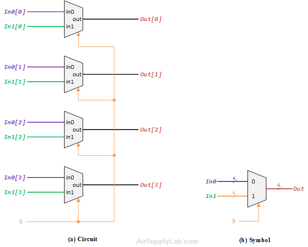
Figure 3: A four-bit wide 2-to-1 Multiplexer
4-to1 1-bit MUX
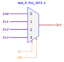
A 4-to-1 MUX takes four inputs and directs a single selected input to output. A 2-bits selection input controls the selection of input. The characteristic table of 4-to-1 MUX is shown below:
| Select Lines | Output | |
|---|---|---|
| S1 | S0 | Out |
| 0 | 0 | In0 |
| 0 | 1 | In1 |
| 1 | 0 | In2 |
| 1 | 1 | In3 |
Figure 4: A 4-to-1 Multiplexer
The logic schematic diagram of 4-to-1 MUX is shown in the following Figure:
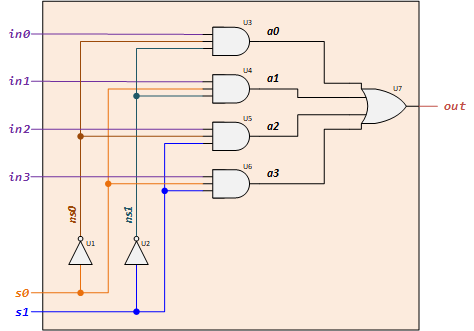
Figure 5: 4-to-1 1-bit MUX Logic Circuit
Lab Experiments
1.1 Connect Switches to LEDR
The DE10-Lite provides ten switches and lights, called SW9-0 and LEDR9-0. The switches can provide input signals, and the lights can be used as output devices. To directly connect each input to the outputs, the buffer gate can be used in this situation. The following diagram shows a simple circuit with ten buffers connecting switches and LEDs.
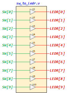
Figure 6: Using Buffers To Connect the SWs to LEDRs
Besides the Gate-Level modeling, we also can use Data Flow modeling to describe the circuit as follow:
assign LEDR[0] = SW[0];
assign LEDR[1] = SW[1];
assign LEDR[2] = SW[2];
assign LEDR[3] = SW[3];
assign LEDR[4] = SW[4];
assign LEDR[5] = SW[5];
assign LEDR[6] = SW[6];
assign LEDR[7] = SW[7];
assign LEDR[8] = SW[8];
assign LEDR[9] = SW[9];
Since there are multiple switches and lights, and they have the same size (bit width), it is convenient to represent them as a vector in the Verilog code, as shown. We have used a single assignment statement for all LEDR outputs, which is equivalent to the individual assignments:
assign LEDR = SW;
Lab Procedures
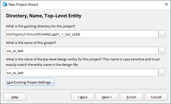
- Launch Intel Quartus Prime and click on File ➤ New Project Wizard to create a new project for your circuit.
- The New Project Wizard dialog will be displayed. Enter the directory and the new name for the project and top-level module name as below:
- Project working directory: <your project home folder>\Lab01.1_SW_LEDR
- Project name: sw_to_ledr
- Top-level module name: sw_to_ledr
- Create a new Verilog HDL file, implement the circuit using gate-level modeling to describe the Figure 6 circuit, and save it to sw_to_ledr.v file.
module sw_to_ledr(SW, LEDR);
input  [9:0] SW;    // Slide Switches
output [9:0] LEDR;  // Red LEDs

// Using Gate-Level modeling to connect SWs to LEDRs


endmodule
- Compile the project by clicking Processing ➤ Start Analysis & Elaboration.
- Open the RTL Viewer to check the connections by clicking the Tools ➤ Netlist Viewers ➤ RTL Viewer.
- If any connection is incorrect, fix it in the sw_to_ledr.v, and redo step 4.
- Import the pin assignment file to your project.
- Compile the project by clicking Processing ➤ Start Compilation.
- Download the compiled object file to the FPGA board using the Quartus Programmer tool.
- Test the circuit's functionality by toggling the switches and observing the LEDs.
Question
- Set the switch to the values shown below (logic-0 means slide down and logic-1 slides up) to see the result on the LEDs. Take pictures of each iteration.
- SW[9:0] = 1111 0000
- SW[9:0] = 0000 1111
- SW[9:0] = 1100 1100
- SW[9:0] = 0101 0101
1.2 Four-bit Wide 2-to-1 Multiplexer
Design a four-bit wide 2-to-1 multiplexer as the following figure — Use switch SW[9] as the S input, switches SW[3:0] as the In0 input, and SW[7:4] as the In1 input. Display the value of the input S on LEDR[9], connect the output Out to LEDR[3:0], and connect the unused LEDR lights to the constant value 0.
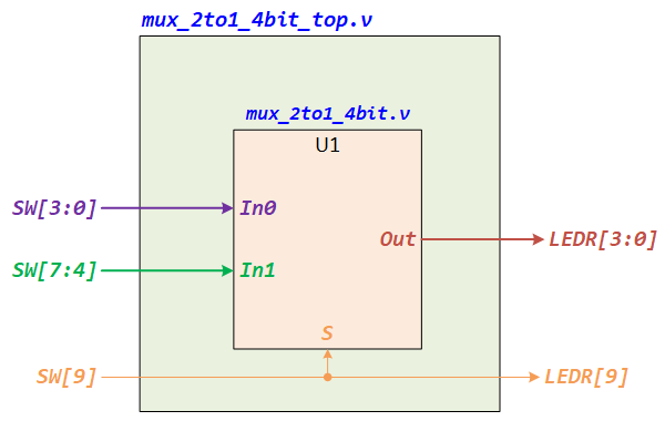
Figure 7: Top Module of a Four-Bit Width 2-to-1 Multiplexer
Lab Procedures
- Create a new Quartus project for your circuit by entering the following information:
- Project working directory: <your Project home folder>\Lab01.2_Multiplexer
- Project name: mux_2to1_4bit
- Top-level module name: mux_2to1_4bit_top
- Create a new Verilog HDL file to implement the top-level module. Type the following Verilog and complete the connections based on Figure 7, then save it to mux_2to1_4bit_top.v
module mux_2to1_4bit_top(SW, LEDR); input [9:0] SW; output [9:0] LEDR; mux_2to1_4bit U1 (.In0(__), .In1(__), .S(__), .Out(__)); // Connect LEDR[9] to SW[9] assign _______; endmodule - Create a new Verilog HDL file to implement the 2-to-1 1-bit MUX by using Gate-level modeling to describe the circuit, as shown in Figure 2(b). Save the file to mux_2to1_1bit.v
module mux_2to1_1bit(in0, in1, s, out); input in0, in1, s; output out; // Using Gate-Level Modeling to desctibe the 2-to-1 1bit MUX circuit here endmodule - Create a new Verilog HDL file to implement the 2-to-1 1-bit MUX by using Gate-level modeling to describe the circuit, as shown in Figure 3(a). Save the file to mux_2to1_4bit.v
module mux_2to1_4bit(In0, In1, S, Out); input [3:0] In0; input [3:0] In1; input S; output [3:0] Out; // Connect four 2-to-1 1bit MUX mux_2to1_1bit U1 (.in0( ), .in1( ), .s( ), .out( ) ); mux_2to1_1bit U2 (.in0( ), .in1( ), .s( ), .out( ) ); mux_2to1_1bit U3 (.in0( ), .in1( ), .s( ), .out( ) ); mux_2to1_1bit U4 (.in0( ), .in1( ), .s( ), .out( ) ); endmodule - Click [Start Analysis & Elaboration] to compile your design. Make sure there are no syntax errors.
- After you perform a successful Analysis & Elaboration, you can view the design in the RTL Viewer by clicking Tools ➤ Netlist Viewers ➤ RTL Viewer. Screenshot the RTL diagrams for top, 2-to-1 4bit, and 2-to1 1bit modules.
- Import pin assignments to the project.
- Fully compile the project by clicking Processing ➤ Start Compilation. After success compelling, program the object file (mux_2to1_4bit_top.sof) to the FPGA board.
- Test the functionality of the four-bit wide 2-to-1 multiplexer by toggling the switches and observing the LEDs.
Question
- Post your RTL diagrams for the top-level module, 2-to-1 4-bit module, and 2-to-1 1-bit module in your report.
- Test your design and fill in the results in the following table.
SW[9] SW[7:4] SW[3:0] LEDR[9] LEDR[3:0] 0 0101 1111 1 0101 1111 0 1100 1001 1 1100 1001 0 0011 0110 1 0011 0110
1.3 Implement 8-to-1 Multiplexer
In this experiment, you will design an 8-to-1 MUX using two 4-to-1 MUX and one 2-to-1 MUX.
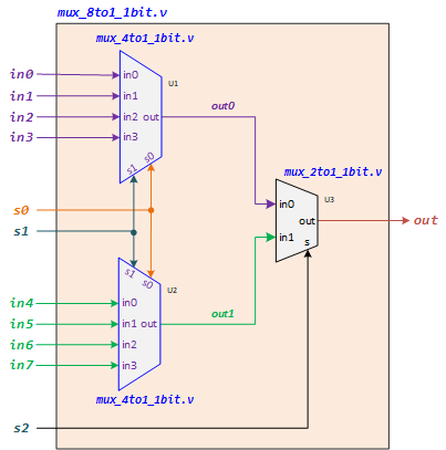
Figure 8: Build an 8-to-1 1-bit MUX using Two 4-to-1 and One 2-to-1 MUXs
Lab Procedures
- Launch Intel Quartus Prime and click on File ➤ New Project Wizard to create a new project for your circuit.
- The New Project Wizard dialog will be displayed. Enter the directory and the new name for the project and top-level module name as below:
- Project working directory: <your project home folder>\Lab01.3_MUX_8TO1
- Project name: mux_8to1_1bit
- Top-level module name: mux_8to1_1bit
- Add the mux_2to1_1bit.v file from the Lab01_2_Multiplexer folder into the project.
- Create a new Verilog HDL file to implement the top-level module. Type the following Verilog and complete the connections based on Figure 8, then save it to mux_8to1_1bit.v.
module mux_8to1_1bit(in0, in1, in2, in3, in4, in5, in6, in7, s0, s1, s2, out); input in0, in1, in2, in3, in4, in5, in6, in7; // Input Pins input s0, s1, s2; // Selection Pins output out; // Output Pin wire out0, out1; // Using Structural (Gate-Level) modeling to implement 8-to-1 MUX mux_4to1_1bit U1 (.in0(), .in1(), .in2(), .in3(), .s0(), .s1(), .out()); mux_4to1_1bit U2 (.in0(), .in1(), .in2(), .in3(), .s0(), .s1(), .out()); mux_2to1_1bit U3 (.in0(), .in1(), .s(), .out()); endmodule - Create a new Verilog HDL file to implement the 4-to-1 1-bit MUX using Gate-level modeling to describe the circuit, as shown in Figure 6. Save the file to mux_4to1_1bit.v.
module mux_4to1_1bit(in0, in1, in2, in3, s0, s1, out);
input  in0, in1, in2, in3;                      // Input Pins
input  s0, s1;                                  // Selection Pins
output out;                                     // Output Pin

wire ns0, ns1, a0, a1, a2, a3;

// Using Gate-Level modeling to implement 4-to-1 MUX


endmodule
- Create a new Verilog HDL file to implement a testbench file. Copy the following code and save it to mux_8to1_1bit_tb.v.
`timescale 1ns/1ps module mux_8to1_1bit_tb(); reg in0, in1, in2, in3, in4, in5, in6, in7; reg s0, s1, s2; wire out; mux_8to1_1bit DUT(.in0(in0), .in1(in1), .in2(in2), .in3(in3), .in4(in4), .in5(in5), .in6(in6), .in7(in7), .s0(s0), .s1(s1), .s2(s2), .out(out)); initial begin in0 = 1'b0; in1 = 1'b1; in2 = 1'b1; in3 = 1'b1; in4 = 1'b0; in5 = 1'b0; in6 = 1'b1; in7 = 1'b1; s0 = 1'b0; s1 = 1'b0; s2 = 1'b0; #1 $display("s2=%d s1=%d s0=%d out=%d \n", s2, s1, s0, out); #5 s0 = 1'b0; s1 = 1'b0; s2 = 1'b1; #1 $display("s2=%d s1=%d s0=%d out=%d \n", s2, s1, s0, out); #5 s0 = 1'b0; s1 = 1'b1; s2 = 1'b0; #1 $display("s2=%d s1=%d s0=%d out=%d \n", s2, s1, s0, out); #5 s0 = 1'b0; s1 = 1'b1; s2 = 1'b1; #1 $display("s2=%d s1=%d s0=%d out=%d \n", s2, s1, s0, out); #5 s0 = 1'b1; s1 = 1'b0; s2 = 1'b0; #1 $display("s2=%d s1=%d s0=%d out=%d \n", s2, s1, s0, out); #5 s0 = 1'b1; s1 = 1'b0; s2 = 1'b1; #1 $display("s2=%d s1=%d s0=%d out=%d \n", s2, s1, s0, out); #5 s0 = 1'b1; s1 = 1'b1; s2 = 1'b0; #1 $display("s2=%d s1=%d s0=%d out=%d \n", s2, s1, s0, out); #5 s0 = 1'b1; s1 = 1'b1; s2 = 1'b1; #1 $display("s2=%d s1=%d s0=%d out=%d \n", s2, s1, s0, out); #5 $stop; end endmodule - Click Start Analysis & Elaboration to compile your design. Make sure there are no syntax errors.
After you perform a successful Analysis & Elaboration, you can view the design in the RTL Viewer by clicking Tools ➤ Netlist Viewers ➤ RTL Viewer. Screenshot the RTL diagrams for mux_8to1_1bit, and mux_4to1_1bit modules. - If there are no errors, click RTL Simulation to simulate and test the 8-to-1 MUX.
- Screenshit the waveform.