
Lesson KB 04: MyDefines.h Explained - Portable Register Definitions for the Tiva C LaunchPads (TM4C123G & TM4C1294)
Introduction
In bare-metal embedded programming on the Tiva™ C Series LaunchPads, we configure every peripheral by writing directly to its hardware registers. Each register is a 32-bit word, and each function is controlled by one or more bit fields inside that word. Without help, our code quickly fills up with "magic numbers" such as GPIOF->DIR = 0x0E; — values that are hard to read, easy to mistype, and almost impossible to maintain.
To solve this, we place all of our register bit-field constants into a single shared header file named MyDefines.h. Every lab in this course includes this one file, so the same meaningful names are available everywhere.
Register access convention (CMSIS struct + MyDefines.h)
Throughout this course, registers are accessed using the CMSIS device-header struct notation supplied by the Keil μVision device header (for example, TM4C123GH6PM.h), such as GPIOA->AFSEL, GPIOA->PCTL, and GPIOA->DEN. This follows the standard Keil μVision convention and keeps the code aligned with the register names in the datasheet.
The two pieces work together as a pair:
- The CMSIS struct selects which register to access — e.g., GPIOF->DIR.
- The MyDefines.h macros supply the bit-field value to write — e.g., _PIN1 | _PIN2 | _PIN3.
Combined, a single line such as GPIOF->DIR = _PIN1 | _PIN2 | _PIN3; reads almost like plain English: "set pins 1, 2, and 3 of Port F as outputs."
Why do we need MyDefines.h?
- Readable, self-documenting code. A line such as GPIOF->DIR = _PIN1 | _PIN2 | _PIN3; tells the reader exactly which pins are set as outputs, without decoding hex by hand.
- No raw hex, fewer bugs. Naming each bit field removes hand-computed hex values, which are one of the most common sources of silent, hard-to-find errors.
- Matches the datasheet. The macro names follow the register and bit-field names in the TM4C datasheet (e.g., GPTMCFG, UARTLCRH), so you can cross-reference the code and the manual side by side.
- Easy to maintain and reuse. A value is defined in exactly one place. Update it once, and every lab that uses it stays correct.
- Portable across two boards. Most register bit positions are identical on both LaunchPads, so the same definitions work on both without change (see below).
One header, two boards
This MyDefines.h is written to work on both the EK-TM4C123GXL (TM4C123G) and the EK-TM4C1294XL (TM4C1294) LaunchPads. Because both devices share the same peripheral IP, the great majority of bit-field definitions are board-common and are used unchanged on either board. Only a few items are truly board-specific — mainly the system-clock setup, the PWM clock divider, and the interrupt (NVIC) number table. For those cases, the board is made explicit in the macro name using a _123G_ or _1294_ tag, for example _IRQ_INT_NUM_123G_GPIOF versus _IRQ_INT_NUM_1294_GPIOF.
How to build up your MyDefines.h
You do not need to type in the entire file at the very beginning. The header is organized into clearly labeled, self-contained blocks — one block per peripheral module (GPIO, PWM, UART, Timer, ADC, I2C, and so on). As you progress through the labs, simply add the block for a module only when you first need that module. This keeps your header small, easy to understand, and directly tied to what you have actually studied.
The GPIO definitions (port enable masks, pin masks, bit masks, and the GPIOMSK() helper) are required by default. Almost every peripheral relies on GPIO pins, so these definitions should always be present in your header from the start. All other module blocks are optional and added on demand.
The Structure of MyDefines.h
Before adding any definitions, first create the file MyDefines.h with the skeleton below. Every definition you add throughout the course lives inside this skeleton.
#ifndef MYDEFINES_H
#define MYDEFINES_H

#endif
The three preprocessor lines form an include guard. When a source file includes MyDefines.h, the guard makes sure its contents are processed only once, even if the header is included (directly or indirectly) more than once. Without it, the same definitions could be seen twice, and the compiler would report redefinition errors.
- #ifndef MYDEFINES_H — “if MYDEFINES_H is not yet defined, process the lines below.”
- #define MYDEFINES_H — define that name, so the next time the file is included, this block is skipped.
- #endif — marks the end of the guarded region.
Whenever you add new definitions to this file later, you must type them before the #endif line (that is, between #define MYDEFINES_H and #endif). Any definition placed after #endif falls outside the include guard and will cause compile errors when you build your program.
So the file always has this shape, and every module block from the next sections is inserted where the blank lines are:
#ifndef MYDEFINES_H
#define MYDEFINES_H

// ---- all your definitions go here, before #endif ----
// (GPIO, PWM, UART, Timer, ADC, I2C, ... added as needed)

#endif
KB 4.1 Definitions for GPIO Configuration
4.1 Definitions for GPIO Configuration
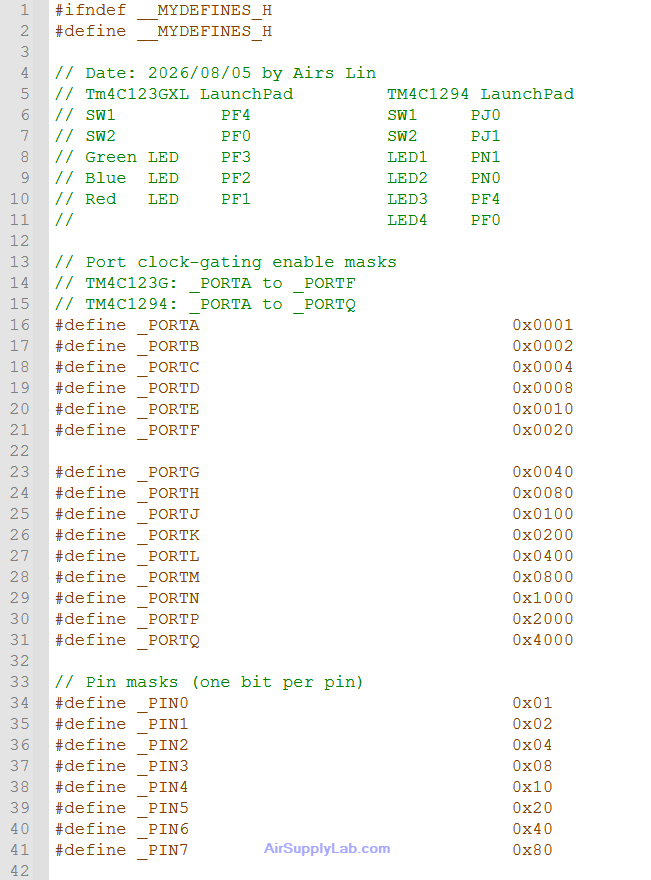
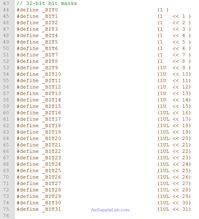
The GPIO block is the foundation of every lab, because nearly every peripheral (UART, PWM, Timer, ADC, I2C, and so on) still needs GPIO pins to reach the outside world. For this reason the GPIO definitions are required by default and should always be present in your MyDefines.h from the very first lab.
These definitions do not configure GPIO by themselves. Instead, they provide the bit-field values that you write into the GPIO registers accessed through the CMSIS device-header structs (GPIOF->DIR, GPIOF->DEN, GPIOF->PCTL, etc.).
Board pin reference
Keep the board pin-mapping comment near the top of this block as a quick reference for the on-board LEDs and switches on each LaunchPad. It generates no code, but it saves you from looking up the schematic every time: on the TM4C123G, the RGB LED is on PF1–PF3 with the two switches on PF4 and PF0, while on the TM4C1294, the four LEDs are on PN1, PN0, PF4, PF0 with the switches on PJ0 and PJ1.
(1) Port clock-gating enable masks
Before a GPIO port can be used, its clock must be enabled in the RCGCGPIO register. Each port mask corresponds to one bit in RCGCGPIO (Port A = bit 0, Port B = bit 1, …). The definitions cover every port on both boards; the TM4C123G uses Ports A–F, while the TM4C1294 adds Ports G–Q.
Typical use:
SYSCTL->RCGCGPIO |= _PORTF; // enable the clock for Port F(2) Pin masks (one bit per pin)
Most GPIO registers are bit-per-pin: bit n controls pin n. The pin masks let you select one or more pins by OR-ing them together, so the code reads like the pin numbers themselves.
Typical use:
GPIOF->DIR |= _PIN1 | _PIN2 | _PIN3;   // PF1, PF2, PF3 as outputs
GPIOF->DEN |= _PIN1 | _PIN2 | _PIN3;   // digital enable
(3) 32-bit bit masks
Some registers use bit positions higher than 7 (for example interrupt, clock, or control registers). The general-purpose bit masks name every bit from 0 to 31, so you never have to write a raw shift by hand.
Typical use:
SYSCTL->RCGCGPIO |= _BIT5; // same as _PORTF (bit 5) → Port F clockIn the bit-mask definitions, the high-bit entries use the unsigned suffixes 1U / 1UL. Shifting a plain 1 (a signed int) into or past the sign bit is undefined behavior in C, so the unsigned form keeps the shift always well defined.
(4) PCTL nibble offsets
The GPIOPCTL register selects the alternate function for each pin using a 4-bit field (one nibble) per pin. The PCTL offset constants give the bit position of each pin’s nibble, so you can place a function number in the correct location.
Typical use (route PA0/PA1 to UART0, whose alternate function number is 1):
GPIOA->PCTL |= (1 << _PCTL_PIN0) | (1 << _PCTL_PIN1);
(5) The GPIOMSK() helper macro
The Tiva GPIO peripheral has a special hardware feature: when you access the GPIODATA register, address bits [9:2] act as a mask. Only the data bits whose address-mask bits are set are actually read or written; all other pins are left untouched. This lets you change a group of pins atomically, without a read-modify-write sequence.
The GPIOMSK() macro builds that masked address for you: it takes the GPIO port base pointer and a pin mask, shifts the mask left by 2 to line it up with address bits [9:2], and adds it to the base as a byte offset.
Typical use:
// Write: drive only PF1..PF3, leave every other pin untouched
*GPIOMSK(GPIOF, _PIN1 | _PIN2 | _PIN3) = _PIN2;   // PF2 high, PF1/PF3 low

// Read: return only the state of PF0 and PF4 (e.g. the two switches)
uint32_t sw = *GPIOMSK(GPIOF, _PIN0 | _PIN4);
Pass the base pointer of the port (for example GPIOF) to GPIOMSK(), not GPIOF->DATA. The macro computes the offset from the port base to the correct masked GPIODATA alias.
The GPIO block — port enable masks, pin masks, bit masks, PCTL offsets, and GPIOMSK() — is the required default content of MyDefines.h. All of these definitions are board-common and work unchanged on both the TM4C123G and the TM4C1294. Every later module block is added on top of this foundation only when a lab requires it.