Lesson KB 04: Heap and Stack Size
Stack is used for static memory allocation and Heap for dynamic memory allocation, both stored in the system's RAM.
- Local variables, function parameters, and function-related information are stored in the Stack memory area;
- The dynamic memory requirements are stored in the Heap memory area.
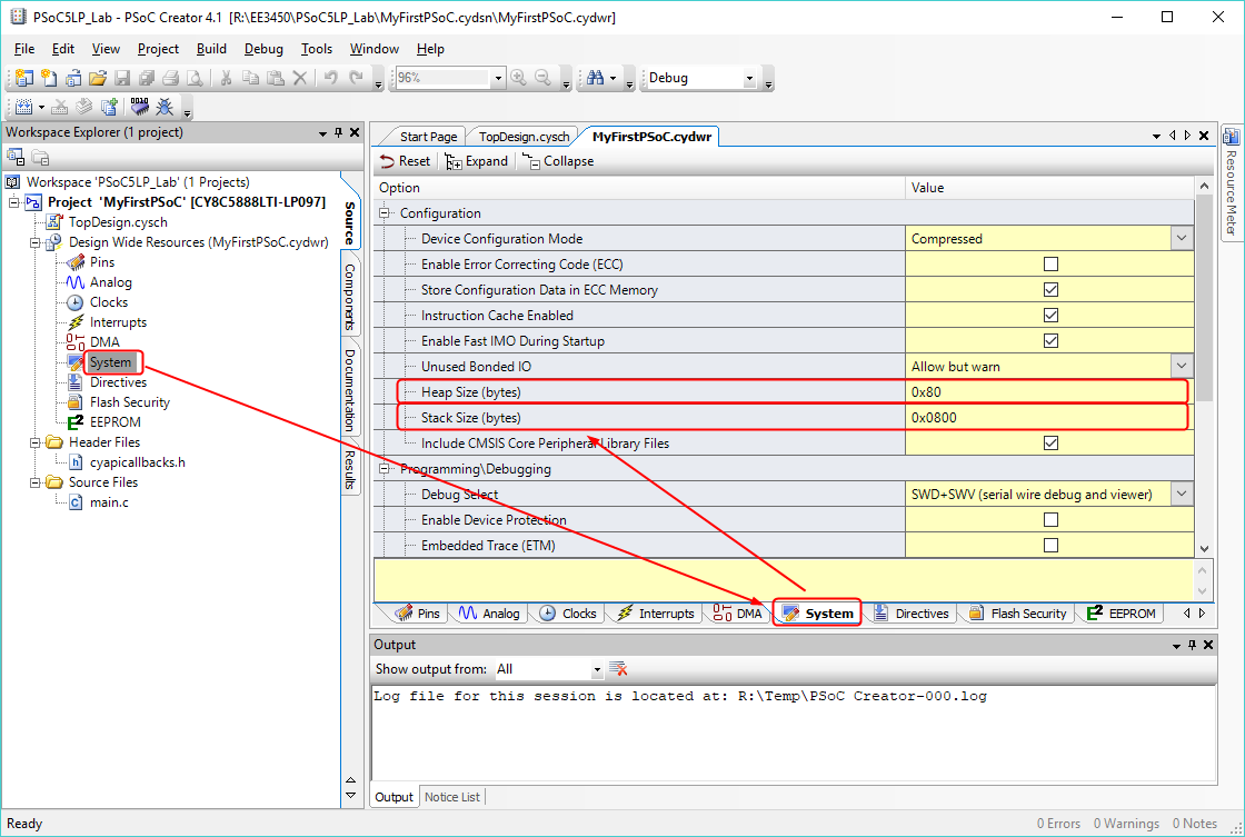
In the PSoC Creator, the default Stack Size is 2K Bytes (0x0800); and the Heap Size is 128 Bytes (0x80). If you are using dynamic memory allocation, you may need to Increase the heap size, and if you are using a lot of local variables, you must increase the Stack size.
On the Workspace Explorer panel, double-click on Design Wide Resources (.cydwr). Then in the .cydwr view, select the System tab. You can change stack and heap size in the Configuration node.