
Lab 00: Lab Requirements
1. Course Introduction and Lab Objectives
1. Course Introduction and Lab Objectives
1.1 About This Course
ELC/ELE/MAN-74 Industrial Wiring and Controls introduces the control circuits that run machines in factories, warehouses, water treatment plants, and commercial buildings. Every conveyor, pump, mixer, packaging machine, and HVAC unit has a control circuit that answers simple questions: When should this motor start? When must it stop? How long should it run? What happens if something goes wrong?
In this course, you will answer those questions with relay logic: control relays, timer relays, push buttons, selector switches, and indicator lamps wired together according to a ladder diagram. Most students in this course have never wired a control circuit before. That is expected. The labs start from the very basics and build up one skill at a time.
1.2 Why Learn Relay Logic?
- It is still everywhere. Relay control panels are installed in existing equipment across every industry. Technicians are expected to read, wire, and repair them.
- It is the foundation of PLC programming. The most common PLC language, Ladder Logic, was designed to look exactly like relay ladder diagrams. If you understand a relay circuit, you already understand how a PLC program works.
- It teaches troubleshooting. With relays, you can see, hear, and measure every contact and coil. This builds the habit of tracing a circuit step by step, a skill you will use throughout your career.
- Safety circuits depend on it. Emergency stops, master control relays, and interlocks are often hard-wired, even in modern PLC-controlled machines.
1.3 Lab Objectives
After completing all of the labs in this course, you will be able to:
- Read and draw ladder diagrams using standard symbols for coils, N.O./N.C. contacts, timer contacts, push buttons, selector switches, and pilot lamps.
- Identify the pins of each relay and timer relay on the lab panel and explain how each contact set (common, N.O., N.C.) changes state when the coil is energized.
- Wire a control circuit from a ladder diagram neatly and correctly, using a wiring table, wire numbers, and the terminal strips on your panel.
- Build the core control patterns used in industry, including start/stop with seal-in (holding) contacts, interlocking, master control relay (MCR), and multi-station control.
- Apply timer relays (On-Delay, Off-Delay, Interval-On, and Multi-Function) to real sequencing problems, and explain their behavior with timing diagrams.
- Test and troubleshoot a circuit using a digital multimeter, both with power off (continuity) and with power on (voltage).
- Design your own control circuits from a written specification, by reusing and combining the patterns learned in earlier labs.
- Work safely and professionally: power off before wiring, verify before energizing, and keep your panel organized and labeled.
1.4 How the Labs Are Organized
The lab manual contains 20 labs arranged in 5 Parts. The labs progress from simple to complex:
- from basic relay circuits to circuits that use several timer relays working together, and
- from one start/stop push-button set to two push-button sets (multi-station control).
Every lab is based on a real industrial application, such as a conveyor, a pump station, or a warning system, so you can see where the circuit is used in the real world.
| Labs | What Is Provided | What You Do |
|---|---|---|
| Labs 01–03 | Complete ladder diagram and complete wiring table (worked examples) | Study the example, wire it, test it, and answer the questions |
| Lab 04 and later | Circuit specification plus step-by-step, rung-by-rung hints | Design the ladder diagram, write the wiring table, then wire and test |
Each lab also explains its key wiring points and how the circuit can be reused in later designs. Keep your completed labs. You will build on them.
1.5 Lab Procedure (Every Lab)
- Read the lab description and the industrial application.
- Draw the ladder diagram on the ladder-grid worksheet.
- Complete the wiring table (Rung #, Wire #, From, To, Purpose).
- Get instructor approval (stamp) on your ladder diagram before you start wiring.
- Wire the circuit with power OFF, checking off each wire in the table.
- Check your wiring with the multimeter (continuity test) before applying power.
- Power on, test every function specified, and demonstrate it to the instructor.
- Answer the lab questions and turn in your worksheet.
1.6 Your Lab Panel
All labs in this course are wired on a control panel that you build yourself at the start of the semester. The panel is built on a 12 in × 20 in × 1/2 in plywood board and holds the control relays, timer relays, push buttons, selector switch, pilot lamps, and terminal strips. You will use the same panel for every lab, so build it carefully. The components are described in Section 4, and the panel requirements are described in Section 6.
2. Lab Safety and Work Rules
2. Lab Safety and Work Rules
2.1 Why Safety Matters on a 24 V Panel
The lab panels run on 24 V DC, a low voltage that will not give you a dangerous shock under normal conditions. However, low voltage does not mean zero risk:
- A short circuit can make wires, terminals, and contacts hot enough to burn skin or melt insulation.
- A wrong connection can permanently damage relays, timer relays, lamps, or the power supply.
- In industry, the same circuits you build here control 120 V, 240 V, and 480 V equipment. The habits you build in this lab are the habits that will protect you on the job.
Treat every panel as if it were live at full industrial voltage. Build safe habits now.
2.2 General Lab Rules
- Wear safety glasses when cutting, stripping, or crimping wire.
- Keep food and drinks away from the workbench.
- Remove rings, watches, and loose jewelry before working on the panel.
- Keep your work area clean. Put wire scraps in the trash, not on the floor or on the panel.
- Never work on a circuit you do not understand. Ask first.
- Report damaged parts, broken tools, or burned wires to the instructor immediately.
2.3 The Golden Rules of Wiring
| # | Rule | Reason |
|---|---|---|
| 1 | Power OFF before you wire. Turn off the 24 V supply before adding, removing, or moving any wire. | A loose wire touching the wrong terminal while powered can cause a short circuit. |
| 2 | Instructor approval before wiring. Your ladder diagram must be stamped before you start. | Most wiring mistakes are design mistakes. Catch them on paper first. |
| 3 | Test before power. Complete the continuity check (Section 2.5) before turning the supply on. | Finds shorts and missing wires without risk. |
| 4 | On one hand, eyes on the panel. When the circuit is powered, watch what happens and keep your hands off the terminals. | You can react immediately if something starts to smoke, spark, or get hot. |
| 5 | Power OFF when you are done. Turn off the supply before you leave the bench, even for a minute. | An unattended live panel is a hazard to others. |
2.4 Connections That Are Never Allowed
The following mistakes can damage equipment. Check your ladder diagram and your panel for each of them every time.
- Never connect L1 directly to L2.
Every rung must have exactly one load (a relay coil, a timer coil, or a lamp) between L1 and L2. A rung with only contacts and no load is a short circuit the moment those contacts close. - Never put two loads in series.
Each coil or lamp needs the full 24 V. Two loads in series each receive only part of the voltage and will not operate correctly. - Never treat L3 as a permanent power supply.
L3 is a controlled bus. It is normally unpowered and receives power from L1 only through a contact, such as the N.O. contact of the master control relay (MCR). Never jumper L1 directly to L3. - Never connect a timer trigger (pins 5 and 6 on TR2 and TR4) to L1, L2, or L3.
The trigger input accepts only a dry contact (a contact with no voltage from the bus) wired directly across pins 5 and 6. Applying bus voltage to these pins can destroy the timer. - Never connect a coil backward.
The coil ground pin must go to L2: CR1 / TR1 / TR3 pin 7, CR2 pin 13, TR2 / TR4 pin 10. CR2 has a built-in LED and is polarity-sensitive. - Never force a relay or timer into or out of its socket while powered, and never bend or pry the pins.
2.5 Checking Your Circuit Before Power-On
With the 24 V supply OFF, set your digital multimeter to continuity (beep) mode and perform these checks:
- L1 to L2: must NOT beep. If it beeps, you have a short circuit. Find it before continuing.
- L3 to L2: must NOT beep.
- L1 to L3: must NOT beep while the MCR is de-energized.
- Press each push button (or turn the selector switch) and repeat check 1. It must still not beep. A beep here means a rung has contacts but no load.
- For each wire in your wiring table, touch the probes to the "From" and "To" terminals. It must beep. Check off the wire in the table.
Only after all checks pass may you ask the instructor for permission to apply power.
2.6 If Something Goes Wrong
If you see smoke, smell burning, hear buzzing or chattering, or feel a hot component:
- Turn the power supply OFF immediately.
- Do not touch any hot components. Let them cool down.
- Notify the instructor.
- Do not reapply power until the cause has been found and corrected.
2.7 Using Your Tools Correctly
Two screwdrivers are required for this lab. The screws on your panel come in two sizes, and each screwdriver is matched to one of them. Using the wrong screwdriver is the most common way to strip a screw head or crack a terminal block.
| Screwdriver | Used For | Tip to Use |
|---|---|---|
| #1: Klein Tools 32581 4-in-1 Electronics Screwdriver  |
DIN-rail terminal blocks (the main terminal strip and the pilot-lamp terminal strip) | Slotted bit that fills the screw slot completely, usually the 1/8 in (3.2 mm) bit. The kit also has a 3/32 in slotted bit and #0 / #00 Phillips bits. |
| #2: Klein Tools 7314 #1 Combo-Tip Driver, 4 in  |
DIN-rail relay / timer socket bases (CR1, CR2, TR1–TR4) | The combo tip fits the combination (Phillips/slotted) screw heads on the socket terminals. |
Screwdriver tips:
- Press the screwdriver straight into the screw head before you turn it. Most stripped screws are caused by a screwdriver that is tilted.
- Back the terminal screw out until the clamp is fully open before you insert the wire.
- Tighten firmly, then tug each wire to confirm it is held. Do not over-tighten: the socket and terminal screws are small and strip easily.
- Never use the #2 combo-tip driver on the terminal blocks. The tip is too wide and can crack the plastic housing.
Other tools:
| Tool | Correct Use | Common Mistakes |
|---|---|---|
Wire stripper |
All lab wiring uses 18 AWG solid (single-conductor) wire. Use the 18 AWG solid hole on the stripper. Strip about 5/16 in (8 mm), or the strip length marked on the terminal, so that no bare copper shows outside the clamp. Insert the solid wire straight into the clamp; no crimp terminals or ferrules are needed. | Using a hole that is too small nicks the copper, and the wire will later break at the nick. Stripping too much leaves bare copper exposed; stripping too little clamps the insulation instead of the copper. |
Digital multimeter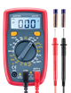 |
Use continuity or resistance with power OFF. Use DC voltage with power ON. | Measuring resistance or continuity on a live circuit gives wrong readings and can damage the meter. |
2.8 Professional Work Habits
- Label every wire with its wire number from the wiring table.
- Do not leave bare copper exposed outside a terminal.
- Route wires neatly. A clean panel is easier to troubleshoot and easier for the instructor to check.
- At the end of each lab, remove your lab wiring as directed, turn off the supply, and return all tools to their places.
3. Control Circuit Fundamentals
3. Control Circuit Fundamentals
Before you wire your first lab, you need to know how the power is distributed on your panel, how the relay contacts are named, and how to read a ladder diagram. This section covers these basics. Refer back to it whenever you are unsure.
3.1 Power Buses: L1, L2, and L3
Your panel has three power buses on the main terminal strip:
| Bus | Voltage | Description |
|---|---|---|
| L1 | +24 V DC | The main supply bus. It is powered whenever the power supply is ON. In a ladder diagram, L1 is the left rail. |
| L2 | 0 V (GND) | The return (ground) bus. Every load (coil or lamp) ends at L2. In a ladder diagram, L2 is the right rail. |
| L3 | +24 V DC only when enabled | A controlled bus. It is normally unpowered. It receives power from L1 only through a contact, usually the N.O. contact of the master control relay (MCR). |
Why do we need L3?
In a real machine, one safety circuit (an emergency stop, a door interlock, or a master ON/OFF switch) must be able to shut down all motors and outputs at once. Instead of placing the stop contact on every rung, we place it on the rung that feeds L3. Everything connected to L3 loses power when the MCR drops out. This is exactly how a master control relay works on a production line.
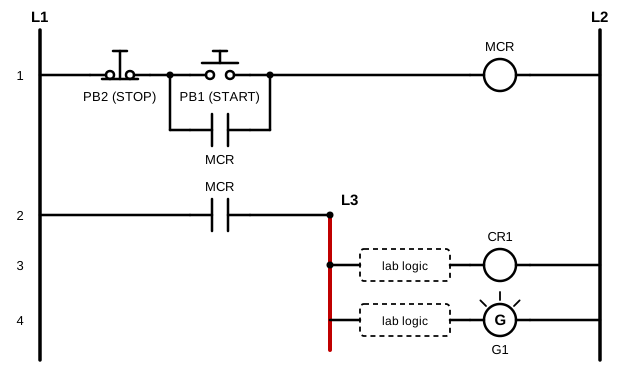
Figure 3-1. L3 is powered from L1 only through the MCR N.O. contact.
3.2 What Is a Relay?
A relay is an electrically operated switch. It has two parts:
- The coil: an electromagnet. When 24 V is applied across the coil, it pulls in a moving armature.
- The contacts: switches that are moved by the armature. When the coil is energized, every contact on the relay changes state simultaneously.
The coil circuit and the contact circuits are electrically separate. This lets one small signal (a push button) control several other circuits at once, and it is the basis of all relay logic.
3.3 Contact Naming Convention
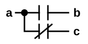
Every relay and timer relay in this course has one or more contact sets. Each contact set has three pins, labeled a, b, and c:
| Pin | Name | Coil OFF (de-energized) | Coil ON (energized) |
|---|---|---|---|
| a | Common (COM) | Always connects to either b or c | |
| a – b | Normally Open (N.O.) | Open (conducts) | Closed |
| a – c | Normally Closed (N.C.) | Closed | Open (conducts) |
When you use a contact, you always use the common pin (a) plus either the N.O. pin (c) or the N.C. pin (b). You may use both the N.O. and the N.C. side of the same set in one circuit, but they share the same common pin.
Example: Contact set CR1A uses pins 1, 3, and 4.
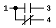
- Pin 1 is the common (a).
- Pins 1–3 form the N.O. contact (a–c).
- Pins 1–4 form the N.C. contact (a–b).
3.4 How We Write Pins and Contacts
| Notation | Meaning |
|---|---|
| CR1:8 | Pin 8 of relay CR1 |
| CR1:1-3 | The contact between pins 1 and 3 of CR1 (an N.O. contact) |
| CR1A, CR1B | Contact set A or B of CR1 |
| PB1:1, PB1:2 | Terminal 1 or 2 of push button PB1 |
| R1:1, R1:2 | Terminal 1 or 2 of red pilot lamp R1 (pin 2 always goes to L2) |
| CR1:8 → TR2:5 | A wire from pin 8 of CR1 to pin 5 of TR2 |
3.5 The "Normal" State
The words normally open and normally closed describe a contact in its shelf state: the relay coil is not energized, and the push button is not pressed.
- An N.O. push button (PB1, PB3) conducts only when pressed. It is used for START.
- An N.C. push button (PB2, PB4) conducts until it is pressed. It is used for STOP.
- The selector switch SSW1 rests in its CENTER (OFF) position, where both of its N.O. contacts, SWL and SWR, are open.
Why is STOP always N.C.? If a wire to an N.C. stop button breaks or comes loose, the circuit opens, and the machine stops. The failure is safe. If STOP were an N.O. button, a broken wire would make the stop button useless, and nobody would know until they needed it. This principle is called fail-safe design.
Important: Ladder diagrams are always drawn in the normal state, even if the circuit will spend most of its time in another state.
3.6 Ladder Diagram Symbols
This course uses standard NEMA (North American) ladder symbols:
| Symbol | Name | Description |
|---|---|---|
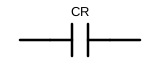 |
N.O. contact | Relay or timer contact that closes when its coil is energized. Labeled with the device name, e.g., CR1. |
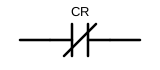 |
N.C. contact | Relay or timer contact that opens when its coil is energized. |
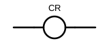 |
Coil | Relay coil (CR1, CR2, MCR) or timer coil (TR1–TR4). Always the last element on the right, next to L2. |
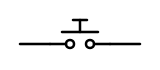 |
N.O. push button | START button (PB1, PB3). The bar is above the contacts. |
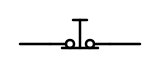 |
N.C. push button | STOP button (PB2, PB4). The bar is below, touching the contacts. |
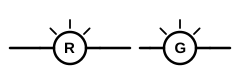 |
Pilot lamp | Indicator lamp. The letter shows the color (R = red, G = green). |
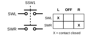 |
Selector switch (3-position) | SSW1 with two N.O. contacts, SWL and SWR, operated by one lever (dashed line). The target table shows which contact is closed (X) in each position. See Section 4.8. |
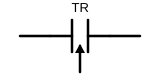 |
N.O.T.C. (Normally Open, Timed Closed) | On-Delay timer contact: closes after the preset time. |
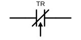 |
N.C.T.O. (Normally Closed, Timed Open) | On-Delay timer contact: opens after the preset time. |
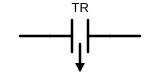 |
N.O.T.O. (Normally Open, Timed Open) | Off-Delay timer contact: closes immediately, opens after the preset time. |
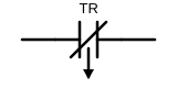 |
N.C.T.C. (Normally Closed, Timed Closed) | Off-Delay timer contact: opens immediately and recloses after the preset time. |
The timer contact symbols and their timing diagrams are explained in detail in Section 4.
3.7 How to Read a Ladder Diagram
- Each horizontal line between L1 and L2 is called a rung. Rungs are numbered from top to bottom.
- Current flows from L1 (left) through the contacts to the load, then to L2 (right).
- Contacts in series (one after another) create AND logic: all must be closed.
- Contacts in parallel (side by side) create OR logic: any one closed is enough.
- Every rung must have exactly one load, placed at the right end.
- A device name (such as CR1) appears once as a coil but may appear many times as contacts. All contacts with the same name change state together when that coil is energized.
3.8 From Ladder Diagram to Wiring
A ladder diagram shows the logic. It does not show the PIN numbers. Before you wire, you translate each symbol into real pins and record each connection in the wiring table.
Example: Pressing PB1 turns on the green lamp G1.
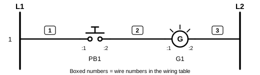
Figure 3-2. Rung 1: pressing PB1 turns on G1.
| ☐ | Rung # | Wire # | From | To | Purpose |
|---|---|---|---|---|---|
| ☐ | 1 | 1 | L1 | PB1:1 | Supply to start button |
| ☐ | 1 | 2 | PB1:2 | G1:1 | Button output to the green lamp |
| ☐ | 1 | 3 | G1:2 | L2 | Lamp returns to the ground |
Follow the same method for every lab: one rung at a time, left to right, one wire per row. Check off each wire as you install it.
4. Lab Components: What Every Student Must Know
4. Lab Components: What Every Student Must Know
Every circuit you build in this course is made from the same small set of components: terminal blocks that distribute power, push buttons and a selector switch that give commands, pilot lamps that show status, control relays that make decisions, and timer relays that add time to those decisions. Before you wire your first lab, you must know each of these components well: what it does, how it works inside, which terminals to use, and what can go wrong.
Industrial electricians and technicians work the same way. Before they troubleshoot or modify a machine, they identify every device in the control panel and look up its terminal numbers. Most wiring mistakes in this lab are not caused by a bad design, but by using the wrong pin: an N.C. contact where an N.O. contact was needed, a contact pin from the wrong set, or a timer terminal that must never be connected to a bus. Learning the components first prevents these mistakes.
Components Covered in This Section
| Group | Components | Job in the Circuit |
|---|---|---|
| Power distribution | 24 V DC power supply, DIN rail, terminal blocks, terminal jumpers, ground terminals | Deliver L1 (+24 V), L2 (GND), and L3 to every rung |
| Input (command) devices | Push buttons PB1–PB4, selector switch SSW1 | Let the operator start, stop, and select |
| Output (indicator) devices | Pilot lamps R1, R2 (red) and G1, G2 (green) | Show the operator what the machine is doing |
| Control relays | CR1, CR2, and their socket bases | Make logical decisions: hold, interlock, switch several circuits at once |
| Timer relays | TR1 (On-Delay), TR2 (Off-Delay), TR3 (Interval-On), TR4 (Multi-Function) | Add time: delay a start, delay a stop, or run for a set time |
How Each Component Is Described
To make the components easy to compare, each one is presented in the same order:
- Photo: what the component looks like on your panel
- Specifications: the ratings and numbers you need to know
- How it works: what happens inside the component
- Terminals and wiring: pin numbers, contact tables, and how to connect a wire
- Checking it with a multimeter: how to prove it works before you use it
- Precautions and common mistakes: what damages the component or makes a circuit fail
Before You Continue
- Read this section with your panel in front of you. Find each component on the panel as you read about it.
- All wiring on the panel uses 18 AWG solid wire.
- Use the correct screwdriver: the Klein Tools 32581 (1/8 in slotted bit) for all DIN-rail terminal blocks, and the Klein Tools 7314 (#1 combo tip) for all relay and timer socket bases.
- Keep the Quick-Reference Card at the end of this section at your bench. You will use it in every lab.
Power Distribution (4.1 – 4.5)
Power Distribution (4.1 – 4.5)
These five components deliver power from the wall outlet to every rung of your circuit: the power supply creates +24 V DC, the DIN rail holds everything in place, and the terminal blocks, jumpers, and ground terminals form the L1, L2, and L3 buses.
4.1 24 V DC Power Supply
Photo
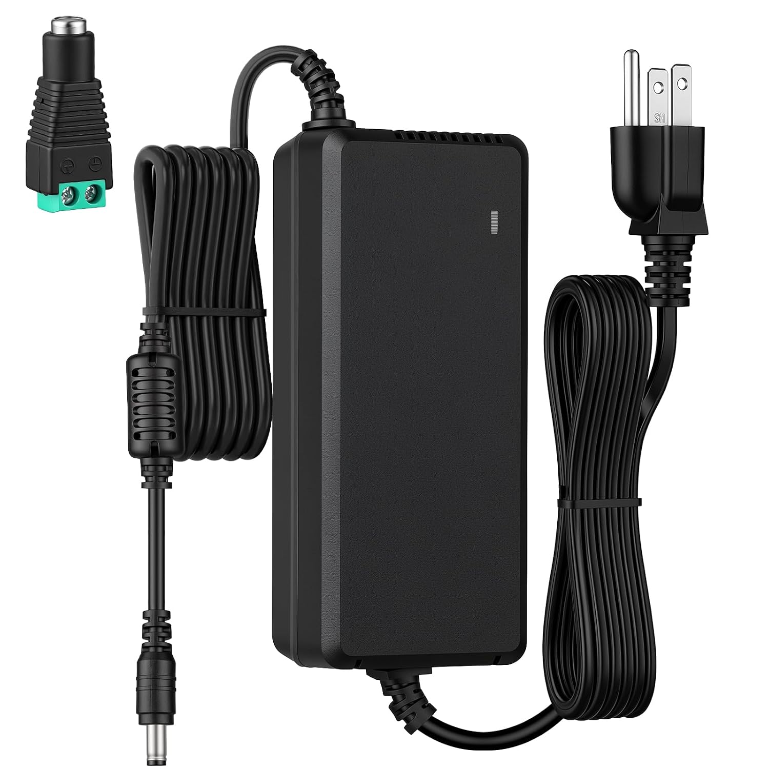
Figure 4.1-1. 24 V DC, 2 A power supply adapter with DC-jack-to-screw-terminal adapter
What It Is
The power supply adapter plugs into a standard 120 V AC wall outlet and converts it to 24 V DC, the control voltage for your entire panel. A small DC-jack-to-screw-terminal adapter turns the round DC plug into two screw terminals, marked + and −, so the supply can be wired to the terminal blocks.
24 V DC is the most common control voltage in modern industrial panels. PLCs, sensors, pilot lamps, and many relays in real machines run on the same voltage you use in this lab.
Specifications
| Input | 120 V AC wall outlet (see the label on the adapter for the full input range) |
| Output voltage | 24 V DC |
| Output current | 2 A maximum |
| Output power | 48 W maximum (24 V × 2 A) |
| Output connection | DC plug → DC-jack-to-screw-terminal adapter (+ and −) |
| Protection | Built-in overload and short-circuit protection |
| Indicator | Power LED on the adapter case |
How It Works
- Inside the adapter, a switching power supply converts 120 V AC to a steady 24 V DC and electrically isolates the output from the wall outlet.
- The + terminal becomes L1 (+24 V) and the − terminal becomes L2 (0 V / GND) on your panel.
- If the load draws too much current or the output is short-circuited, the built-in protection shuts down the output, and the power LED goes out. The adapter is protecting itself and your panel: it is telling you that something in your circuit is wrong.
Is 2 A Enough?
Yes, with a good margin. The largest load on the panel is CR1: its 24 V AC coil draws about 0.5 A when operated on 24 V DC (Section 4.11). Every other coil and pilot lamp draws only a small current; each lamp, for example, draws about 12 mA (Section 4.9). Even with every coil and lamp on the panel energized at the same time, the total current stays around 1 A or less, about half of what the supply can deliver.
Wiring the Power Supply to the Panel
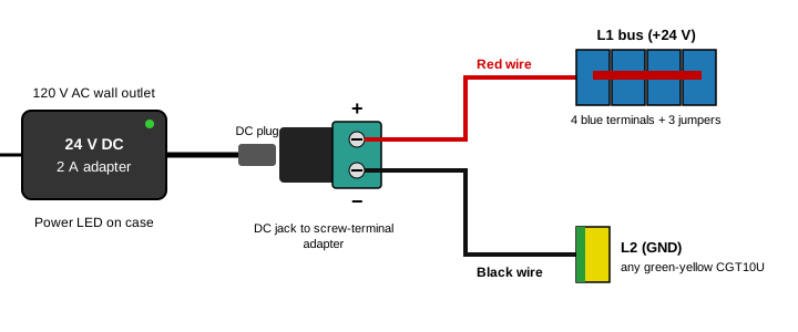
Figure 4.1-2. Connecting the power supply to L1 and L2
| From | To | Wire Color | Purpose |
|---|---|---|---|
| Adapter + | L1 bus (any of the 4 jumpered blue terminals) | Red | +24 V supply |
| Adapter − | L2 (any green-yellow CGT10U terminal) | Black | 0 V return (GND) |
Wire Color Code for the Whole Panel
The same colors are used in every lab so that anyone can recognize a wire's job at a glance:
| Wire Color | Used For |
|---|---|
| Red | L1 (+24 V) |
| Black | L2 (GND), including every coil negative (−) terminal connected to L2 |
| Orange | Relay and timer coil positive (+) terminals |
| Any other color | All other control wires |
Checking the Power Supply with a Multimeter
- Before connecting the adapter to the panel, plug it into the wall outlet. The power LED should light.
- Set the meter to DC volts. Put the red probe on the adapter's + terminal and the black probe on the − terminal. The reading should be about +24 V.
- If the reading is −24 V, the probes are reversed. Check which terminal is actually + before wiring it to L1.
- Unplug the adapter, wire it to the panel as shown in Figure 4.1-2, then plug it in and measure between any L1 terminal and any L2 terminal. You should read about +24 V again.
Precautions and Common Mistakes
- Unplug before you wire. "Power OFF" in this lab means the adapter is unplugged from the wall outlet. Unplug it before adding, removing, or moving any wire.
- Reversed polarity. + must go to L1 and − to L2. Relays and timers with built-in LEDs are polarity-sensitive and may not operate correctly when reversed. Always check with the meter first.
- The power LED went out. Unplug the adapter immediately. Find and fix the short circuit (most often a rung with contacts but no load, or L1 wired to a green-yellow terminal) before you plug it back in. Do not keep plugging it in to "see if it works now."
- Loose adapter terminals. The screws on the DC-jack adapter are small. Tighten them with the Klein 32581 and tug-test each wire.
- DC plug not fully inserted. A partly inserted plug can cause the panel to flicker on and off. Push it in all the way.
- Never open the adapter case. The inside is connected to 120 V AC.
4.2 DIN Rail
Photo
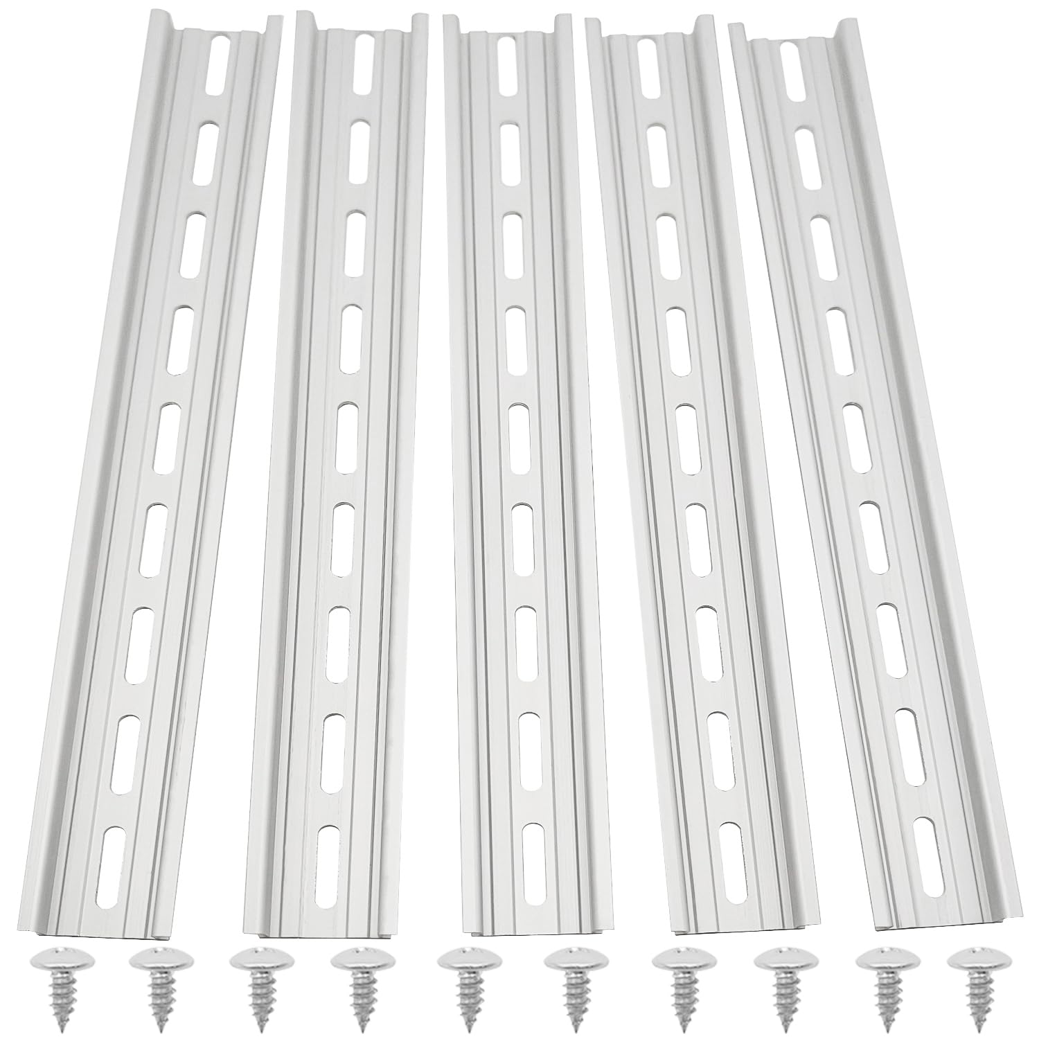
Figure 4.2-1. Slotted aluminum DIN rails with mounting screws
What It Is
A DIN rail is a standardized metal rail onto which everything in a control panel snaps. The rail used in this lab is the 35 mm "top-hat" rail (also called TS35), defined by the international standard EN 60715. Because the size is standardized, relays, timers, terminal blocks, circuit breakers, and power supplies from any manufacturer fit the same rail.
DIN rails make an industrial panel easy to build and service. A failed device can be unsnapped and replaced in seconds, and new devices can be added without drilling new holes.
Specifications
| Type | 35 mm top-hat rail (TS35), slotted | |
| Material | Aluminum (electrically conductive) | |
| Width × height | 35 mm × 7.5 mm (1.38 in × 0.30 in) | |
| Rails on your panel | 12 in (30 cm), top: relay and timer socket bases (CR1, CR2, TR1–TR4) 8 in (20 cm), bottom: main terminal strip (L1, L3, push buttons, selector switch) 4 in (10 cm), right: pilot-lamp terminal strip (R1, G1, R2, G2) |
12 in (30 cm), 8 in (20 cm), and 4 in (10 cm) |
| Mounting slots | 4 mm wide slots along the center; mounted with the included screws | |
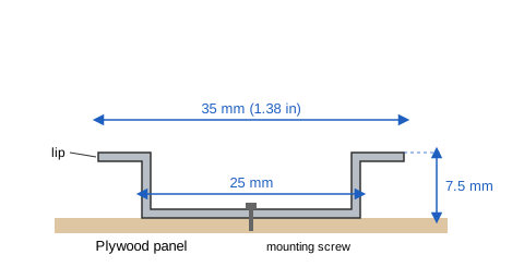
Figure 4.2-2. Cross-section of the 35 mm top-hat DIN rail
How Devices Mount on the Rail
Every DIN-rail device has a fixed hook on its bottom edge and a spring latch on its top edge. The hook grips the lower lip of the rail, and the latch snaps over the upper lip.
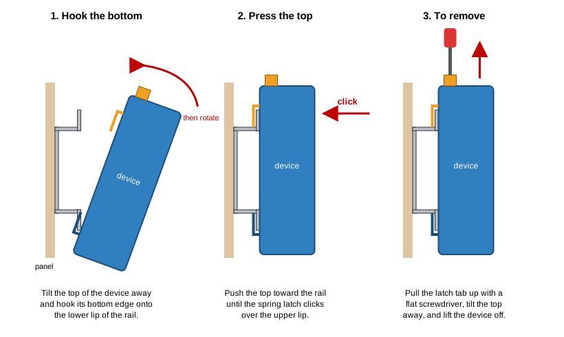
Figure 4.2-3. Mounting and removing a device on the DIN rail
- Hook the bottom. Tilt the top of the device away from the rail and hook its bottom edge onto the lower lip of the rail.
- Press the top. Rotate the device toward the rail and press the top until the spring latch clicks over the upper lip. Pull gently on the device: it must not come off.
- To remove. Insert a flat screwdriver into the latch tab at the top, pull the latch up to release it, tilt the top of the device away from the rail, and lift the bottom off the lower lip. The small slotted bit of the Klein 32581 works well for terminal blocks.
This method applies to the terminal blocks, the ground terminals, and the relay and timer socket bases. The socket bases are snapped directly onto the rail; no hold-down clips are used on this panel.
Which DIN Rails Are Part of L2
The rails are aluminum, so they conduct electricity. Every green-yellow CGT10U ground terminal clamps onto its rail with a metal foot, and all CGT10U terminals on the panel are connected together as L2 (GND). As a result:
- The bottom (8 in) rail and the right (4 in) rail carry CGT10U terminals, so these two rails are at L2.
- The top (12 in) rail holds only the relay and timer socket bases. It has no CGT10U, so it is not connected to any bus.
Warning: Never let a bare L1 or L3 wire, a loose strand, or a dropped screw touch the bottom or right rail. Because those rails are L2, this is a direct short circuit, and the power supply LED will go out. Treat the top rail the same way: bare copper should never touch any metal rail.
Checking with a Multimeter
With the power supply unplugged, set the meter to continuity:
| Probes On | Expected Reading |
|---|---|
| Bottom rail – any green-yellow CGT10U terminal | Beep (the rail is L2) |
| Right rail – any green-yellow CGT10U terminal | Beep (the rail is L2) |
| Top rail – any green-yellow CGT10U terminal | No beep (no CGT10U on the top rail) |
| Any rail – any L1 or L3 terminal | No beep |
A beep between the rail and L1 or L3 means something is touching the rail. Find it before you plug in the power supply.
Precautions and Common Mistakes
- Device not fully latched. A device that is only hooked at one edge can fall off when you press a button or pull a wire. Always listen for the click and the pull test.
- Prying too hard. Pull the latch only until it releases. Forcing it can break the plastic latch spring.
- Gaps between terminal blocks. Slide the terminal blocks tightly together. A gap lets them tilt, making the jumpers hard to insert.
- Loose rail. If the rail moves, tighten its mounting screws before wiring. A loose rail strains every wire connected to it.
4.3 Terminal Blocks (Linergy TR)
Photo
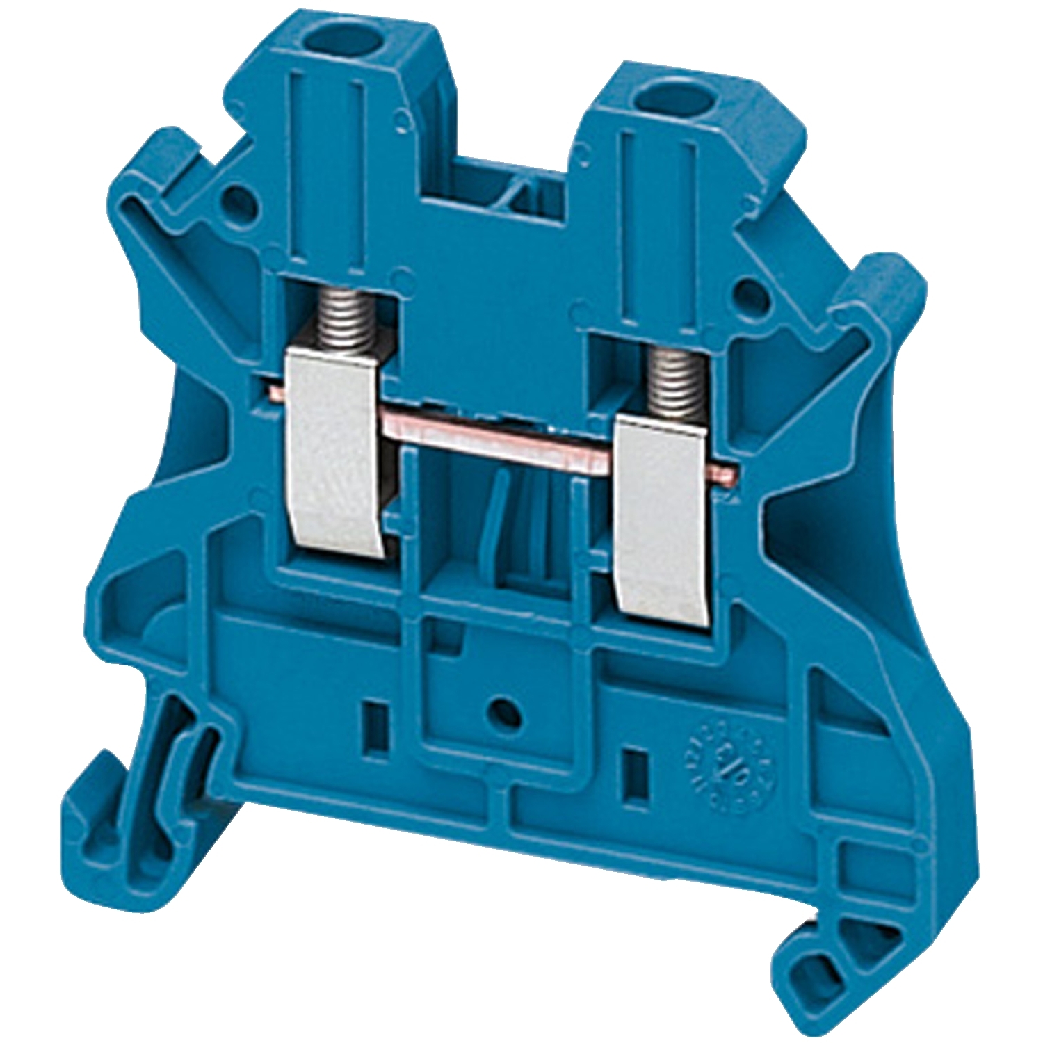 Figure 4.3-1. NSYTRV22BL (blue) |
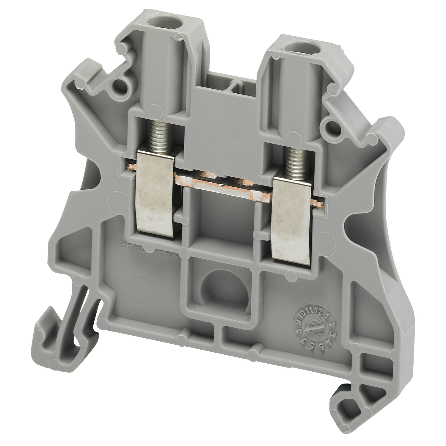 Figure 4.3-2. NSYTRV22 (grey) |
What It Is
A feed-through terminal block is a small insulated block that snaps onto the DIN rail and has two screw-clamp connection points, one on each side. A wire clamped on one side is electrically connected to a wire clamped on the other side. Terminal blocks give every wire in the panel a neat, labeled, and removable connection point, so wires never need to be spliced or twisted together.
On your panel, every push-button contact, every selector-switch contact, and every pilot-lamp terminal is permanently wired to its own terminal block. In the labs, you connect your circuit to these terminal blocks, never directly to the buttons, switches, or lamps.
Specifications
| Manufacturer / Series | Schneider Electric, Linergy TR |
| Models | NSYTRV22BL (blue), NSYTRV22 (grey) |
| Type | Feed-through (pass-through), screw clamp |
| Connection points | 2 (one on each side) |
| Rated wire size | 2.5 mm²; accepts 26–12 AWG solid or stranded copper |
| Mounting | Snaps onto a 35 mm DIN rail (Section 4.2) |
| Wire used in this lab | 18 AWG solid |
| Screwdriver | Klein Tools 32581, 1/8 in (3.2 mm) slotted bit |
The blue and grey models are identical except for color. The color tells you what the terminal is used for.
How It Works
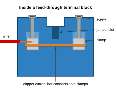
Figure 4.3-3. Inside a feed-through terminal block
- Each connection point has a screw and a metal clamp. Tightening the screw raises the clamp and presses the wire against the copper current bar.
- The current bar runs through the block, so the two points on one terminal block are always connected.
- Neighboring terminal blocks are insulated from each other. Placing two terminals side by side on the rail does not connect them.
- The only way to connect neighboring terminal blocks together is with a terminal jumper. On your panel, the jumper legs are clamped in the screw clamps of the L1 and L3 terminals (Section 4.4).
Color Code on Your Panel
| Terminal | Used For |
|---|---|
| Blue, 4 joined by 3 jumpers | L1 bus (+24 V, from the power supply) or L3 bus (controlled bus, fed through a contact) |
| Blue, single | Terminal 1 of each push button (PB1:1, PB2:1, PB3:1, PB4:1), terminal 1 of each selector-switch contact (SWL:1, SWR:1), and the + terminal of each pilot lamp (R1:1, G1:1, R2:1, G2:1) |
| Grey | Terminal 2 of each push button (PB1:2, PB2:2, PB3:2, PB4:2), terminal 2 of each selector-switch contact (SWL:2, SWR:2), and the − terminal of each pilot lamp (R1:2, G1:2, R2:2, G2:2) |
| Green-yellow (CGT10U) | L2 (GND), see Section 4.5 |
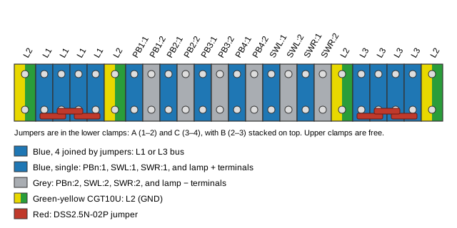
Figure 4.3-4. Color layout of the main terminal strip (the complete panel layout is given in Section 5)
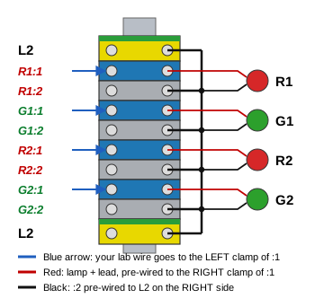
Figure 4.3-5. Color layout of the pilot-lamp terminal strip (4 in rail)
Memory tip: a single blue terminal is always pin :1 of a device, and a grey terminal is always pin :2. A group of four blue terminals joined by jumpers is always a power bus.
How to Connect a Wire
- Unplug the power supply.
- Strip about 5/16 in (8 mm) of insulation from the 18 AWG solid wire (Section 2.7).
- Using the Klein 32581 with the 1/8 in slotted bit, turn the screw counterclockwise until the clamp is fully open.
- Push the bare copper straight into the wire opening until the insulation reaches the terminal body.
- Turn the screw clockwise and tighten it firmly.
- Tug the wire. It must not move, and no bare copper should be visible outside the terminal.
Two Wires in One Clamp
A clamp is large enough for two wires when a circuit needs it. To connect two wires to one clamp:
- Strip both wires 5/16 in (8 mm) and twist the two bare ends together.
- Open the clamp fully, insert both ends together, and tighten firmly.
- Tug each wire separately. Neither may move. Two loose ends side by side can leave one of them unclamped, even though the screw feels tight.
- Check each wire with the multimeter (continuity mode): one probe on the terminal screw, the other on the wire's far end. Each wire must beep (see below).
On the L1 and L3 buses, connect the control wires only to the clamps that do not hold a jumper leg (see Section 4.4).
Checking with a Multimeter
With the power supply unplugged, set the meter to continuity:
| Probes On | Expected Reading |
|---|---|
| Left screw – right screw of the same terminal | Beep (one terminal is one point) |
| Two neighboring terminals with no jumper (for example, PB1:1 – PB1:2) | No beep (the button is released and the terminals are insulated) |
| Any two of the four L1 terminals | Beep (joined by jumpers) |
| Any L1 terminal – any L3 terminal | No beep |
To check that a wire is really clamped, touch one probe to the terminal screw and the other to the bare copper at the far end of the wire. It must beep.
Precautions and Common Mistakes
- Wire inserted beside the clamp. If the clamp is not fully opened, the wire can slide past it. The screw feels tight, but the wire has no connection. Always open the clamp fully and tug-test.
- Clamping the insulation. If the strip length is too short, the clamp squeezes the insulation instead of the copper. The wire looks connected, but does not conduct.
- Too much bare copper. If the strip length is too long, bare copper protrudes from the terminal and can touch a neighboring terminal or the DIN rail (L2).
- Assuming neighboring terminals are connected. They are not, unless a jumper joins them.
- Wrong screwdriver or over-tightening. Use the Klein 32581, not the 7314. Firm is enough; too much force strips the screw or cracks the housing.
4.4 Terminal Jumpers
Photo
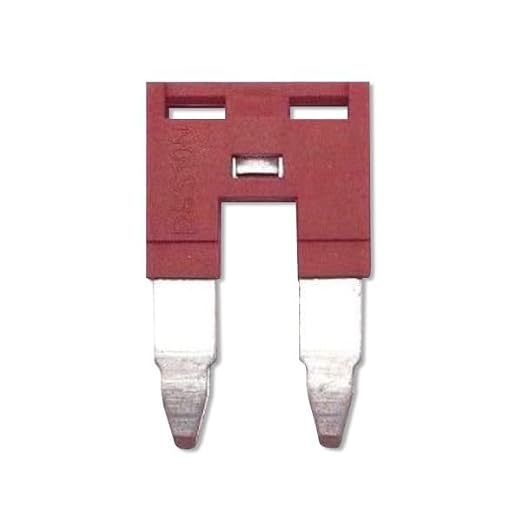
Figure 4.4-1. Dinkle DSS2.5N-02P two-pole jumper
What It Is
A terminal jumper (also called a bridge or shorting bar) is a small insulated handle with two metal legs. It connects two neighboring terminal blocks electrically, without any wire. Jumpers are the standard way to build a power bus on a terminal strip: a row of terminals that all carry the same signal.
In an industrial panel, jumpers are used to distribute +24 V, 0 V, or a common signal to multiple terminals simultaneously. They are faster to install than wires, always the right length, and easy to see and check.
Specifications
| Manufacturer / Model | Dinkle DSS2.5N-02P |
| Poles | 2 (connects two neighboring terminals) |
| Color | Red handle, metal legs |
| Used with | The blue Linergy TR terminal blocks of the L1 and L3 buses (Section 4.3) |
| Mounting on this panel | Legs clamped in the screw clamps of the terminals |
| Quantity on the panel | 6 (3 for the L1 bus, 3 for the L3 bus) |
This jumper was designed to press into the center jumper slot of Dinkle terminal blocks. Its legs are too short to reach the current bar through the jumper slot of the Linergy TR terminals, so on your panel the legs are inserted into the screw clamps instead, just like a wire.
How It Works
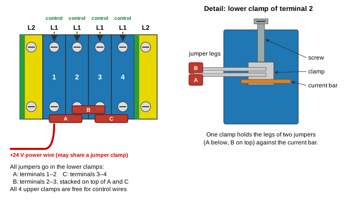
Figure 4.4-2. Three jumpers in the lower clamps join four terminals into one bus
- Each jumper leg is inserted into a screw clamp. When the screw is tightened, the clamp presses the leg against the terminal's copper current bar, exactly as it would press a wire.
- All three jumpers go in the lower clamps:
- Jumper A: terminals 1–2
- Jumper C: terminals 3–4
- Jumper B: terminals 2–3, stacked on top of A and C. The lower clamps of terminals 2 and 3 each hold two jumper legs.
- The chain A → B → C connects all four terminals. They are now on one bus.
- Because every jumper is in the lower clamps, all four upper clamps are free for control wires.
- The L1 and L3 buses are each built this way. The green-yellow CGT10U terminals at the ends of each group are not jumpered; they keep L1 and L3 separated from L2 and from each other.
Where to Connect Wires on a Jumpered Bus
| Wire | Where It Goes |
|---|---|
| +24 V power wire (red, from the power supply to L1) | May share a clamp that already holds a jumper leg (Section 4.1). |
| Control wires (all other wires connected to L1 or L3, including the L3 feed wire from the MCR contact) | Only the upper clamps. All four upper clamps are free because every jumper is in the lower clamps. |
Never put a control wire in a clamp that holds a jumper leg. A clamp holding two different conductors grips each of them less firmly. If the control wire is ever removed, the jumper leg can loosen with it, breaking the bus.
Installing and Removing a Jumper
The jumpers are installed during panel assembly (Section 5). You will not normally move them during the labs.
- Unplug the power supply.
- Open the clamps. Using the Klein 32581, fully open the lower clamps at all four terminals.
- Insert A and C. Slide jumper A into the lower clamps of terminals 1–2 and jumper C into the lower clamps of terminals 3–4, until each red handle touches the terminal bodies.
- Insert B on top. Slide jumper B into the lower clamps of terminals 2–3, on top of the legs of A and C.
- Tighten all four lower clamps firmly. The clamps of terminals 2 and 3 now hold two legs each.
- Tug each jumper. None of them may move.
- To remove: loosen the clamp screws completely, pull out jumper B first, then A and C. Pull each jumper straight out; do not rock it sideways, or the legs can bend.
Checking with a Multimeter
With the power supply unplugged, set the meter to continuity:
| Probes On | Expected Reading |
|---|---|
| L1 terminal 1 – L1 terminal 4 | Beep (all three jumpers conduct) |
| L3 terminal 1 – L3 terminal 4 | Beep |
| Any L1 terminal – the CGT10U next to it | No beep |
| Any L1 terminal – any L3 terminal | No beep (L3 is fed only through a contact) |
Measuring from terminal 1 to terminal 4 tests all three jumpers at once. If it does not beep, measure 1–2, 2–3, and 3–4 separately to find the jumper whose clamp screw is loose.
Precautions and Common Mistakes
- Control wire in a jumper clamp. Only the +24 V power wire may share a jumper clamp. All control wires go to the upper clamps.
- Loose clamp screw. A jumper leg that is not clamped tightly may conduct only sometimes, causing a circuit that works one minute and fails the next. Tug-test every jumper.
- Never jump two different signals. A jumper between an L1 terminal and a push-button, lamp, or L3 terminal permanently connects those points. A jumper from L1 to L2 is a direct short circuit.
- Never use a jumper to "bypass" a contact or button while testing. Use the multimeter instead.
- Bent legs. Do not reuse a jumper with bent legs. It will not clamp properly.
4.5 Ground Terminals (CGT10U)
Photo
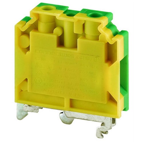
Figure 4.5-1. Connectwell CGT10U ground terminal
What It Is
The CGT10U is a ground terminal block. It looks like a feed-through terminal block, but it is green-yellow, the international color for a grounding conductor, and it has a metal mounting foot that clamps directly onto the metal DIN rail. Any wire clamped in a CGT10U is electrically connected to the rail.
On your panel, the green-yellow terminals are the L2 (0 V / GND) connection points. All CGT10U terminals on the panel are connected together, so any green-yellow terminal can be used as L2.
Specifications
| Manufacturer / Model | Connectwell CGT10U |
| Type | Screw-clamp ground terminal block |
| Color | Green-yellow |
| Connection points | 2 (one on each side) |
| Wire range | 0.2–10 mm² (18 AWG is within range) |
| Width | 10 mm (about twice as wide as a Linergy TR terminal) |
| Mounting | 35 mm DIN rail; the metal foot connects the terminal to the rail |
| Screwdriver | Klein Tools 32581, 1/8 in (3.2 mm) slotted bit |
How It Works

Figure 4.5-2. Inside the CGT10U: the wire is connected to the DIN rail
- Like a feed-through terminal, the CGT10U has two screw clamps joined by a metal bar.
- Unlike a feed-through terminal, the metal bar is also joined to the metal foot. When the terminal snaps onto the rail, the foot grips the rail and makes an electrical connection.
- As a result, every wire in a CGT10U, the rail it is mounted on, and every other CGT10U on the same rail are all the same point: L2.
- The panel has two rails with CGT10U terminals: the bottom (8 in) terminal-block rail and the right (4 in) lamp rail. They are separate rails, so one black L2 bonding wire connects a CGT10U on the bottom rail to a CGT10U on the right rail. This wire is what makes all CGT10U terminals on the panel one L2.
- The top (12 in) relay and timer rail has no CGT10U and is not connected to L2.
Where the CGT10U Terminals Are on Your Panel
- At both ends of the L1 bus (four jumpered blue terminals).
- At both ends of the L3 bus.
- At both ends of the pilot-lamp terminal strip.
Because they sit between the terminal groups, the CGT10U terminals also act as separators: they keep the L1 bus, the push-button terminals, and the L3 bus apart from one another.
Figure 4.5-3. The green-yellow CGT10U terminals on the main terminal strip (same layout as Figure 4.3-4)
What Connects to L2
| Wire | From | Wire Color |
|---|---|---|
| Power supply return | Power supply adapter (−) terminal (Section 4.1) | Black |
| Coil returns | The − terminal of every relay and timer coil: CR1:7, CR2:13, TR1:7, TR2:10, TR3:7, TR4:10 | Black |
| Lamp returns (pre-wired) | The grey lamp (−) terminals: R1:2, G1:2, R2:2, G2:2. These are wired to L2 on the lamp rail when the panel is built; you do not add them in the labs. | Black |
Nothing else ever connects to a green-yellow terminal. In a ladder diagram, L2 is the right rail; every wire that ends at the right rail ends at a CGT10U.
How to Connect a Wire
Connect a wire exactly as you would to a Linergy TR terminal (Section 4.3): unplug the power supply, strip 5/16 in (8 mm), open the clamp fully with the Klein 32581, insert the wire, tighten firmly, and tug-test. A CGT10U clamp is large enough for two wires: twist the two stripped ends together first, insert them together, tighten, then tug each wire separately and check each one with the multimeter (Section 4.3). If the nearest CGT10U is full, use any other green-yellow terminal; they are all L2.
Checking with a Multimeter
With the power supply unplugged, set the meter to continuity:
| Probes On | Expected Reading |
|---|---|
| Any CGT10U – any other CGT10U on the same rail | Beep (connected through the rail) |
| A CGT10U on the bottom rail – a CGT10U on the right rail | Beep (connected by the black L2 bonding wire) |
| Any CGT10U – the DIN rail | Beep |
| Any CGT10U – any L1 terminal | No beep |
| Any CGT10U – any L3 terminal | No beep |
A beep between L2 and L1 is a short circuit. Do not plug in the power supply until you find it.
Green-Yellow in the Real World
In industrial panels, green-yellow terminals are normally used for the protective earth (PE) conductor, which connects the metal enclosure and DIN rails to the building's ground for safety. Many 24 V DC control systems also connect their 0 V line to PE at one point. On this low-voltage training panel, the green-yellow terminals are used as the 0 V (L2) connection points, which is why the DIN rail is at L2 (Section 4.2).
Precautions and Common Mistakes
- Never connect L1, L3, or any control wire to a green-yellow terminal. The wire would be connected to every L2 point on the panel and to the DIN rail. Connecting L1 there is a direct short circuit, and the power supply LED will go out.
- Only return (negative) wires go to L2: the negative (−) output of the power supply, the negative (−) terminal of every relay and timer coil, and the negative (−) terminal of every pilot lamp. All of these wires are black.
- Terminal not fully latched. If the metal foot is not clamped firmly onto the rail, the CGT10U loses its connection to the rail and to the other L2 terminals. Listen for the click and pull-test (Section 4.2).
- Two wires inserted separately. When two wires share a CGT10U clamp, twist their stripped ends together before inserting them. Two loose ends side by side can leave one of them unclamped. Tug-test each wire.
- Missing or loose L2 bonding wire. If the black wire between the bottom rail and the right rail is loose, the lamp returns lose their connection to L2 and the lamps will not light, even though everything else works.
Input Devices (4.6 – 4.8)
Input Devices (4.6 – 4.8)
Input devices are how the operator gives commands to the machine: START, STOP, or a choice between two actions. Each input device on your panel has one or more contacts that are pre-wired to the main terminal strip. In a ladder diagram, these contacts appear on the left side of a rung, between L1 (or L3) and the coil or lamp they control.
Photo
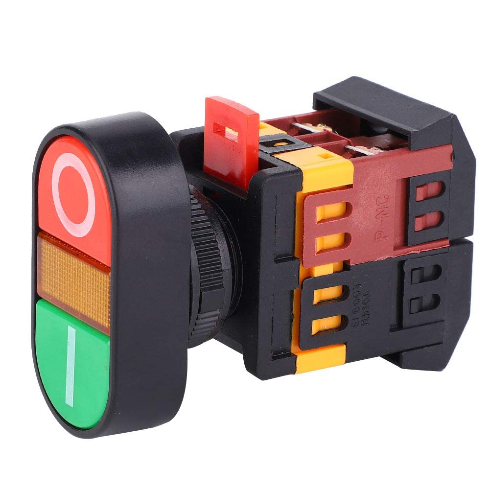
Figure 4.6-1. Push-button set 1: twin push button with indicator (22 mm)
What It Is
This is a twin push button: two momentary push buttons, a green START button, and a red STOP button, in one 22 mm panel-mount housing. Twin push buttons are common on machine control panels because a single compact device provides the operator with both START and STOP in one place.
| Button | Marking | Contact | Function | Terminal Strip |
|---|---|---|---|---|
| PB1 | Green, "I" | N.O. | START | PB1:1 (single blue), PB1:2 (grey) |
| PB2 | Red, "O" | N.C. | STOP | PB2:1 (single blue), PB2:2 (grey) |
The symbols I (ON) and O (OFF) are the international (IEC 60417) power symbols. You see them on machines, power supplies, and power strips around the world.
Specifications
| Type | Twin momentary push button with indicator |
| Mounting size | 22 mm panel hole |
| Action | Momentary (spring return) |
| Contacts | 1 N.O. contact block (green I button) + 1 N.C. contact block (red O button) |
| Contact rating | Far above the 24 V DC coil and lamp loads on your panel |
| Indicator | Amber window between the buttons, 220 V lamp: not wired, not used |
How It Works
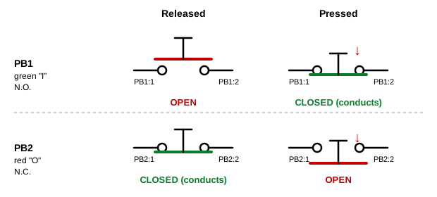
Figure 4.6-2. Contact states of PB1 (N.O.) and PB2 (N.C.)
- Each button pushes the plunger of its own contact block, which is behind the panel. Inside the block, a spring-loaded bridge connects or disconnects the two contact terminals.
- PB1 (N.O.): The bridge is held away from the contacts. Pressing the green button pushes the bridge onto the contacts, and PB1:1–PB1:2 conducts only while the button is held.
- PB2 (N.C.): The bridge rests on the contacts. Pressing the red button pushes the bridge away, and PB2:1–PB2:2 opens only while the button is held.
- Both buttons are momentary: a spring returns the button and its contact to the normal state as soon as you let go. To keep a machine running after START is released, the circuit needs a seal-in (holding) contact from a relay wired in parallel with PB1 (Section 4.11).
Why STOP is N.C.: if a wire to PB2 breaks or comes loose, the circuit opens, and the machine stops. A broken STOP circuit failsafe (Section 3.5).
Ladder Diagram Symbols
|
PB1: N.O. push button (START). The bar is above the contacts. |
|
PB2: N.C. push button (STOP). The bar is below, touching the contacts. |
Checking with a Multimeter
With the power supply unplugged, set the meter to continuity and measure at the terminal strip:
| Probes On | Button Released | Button Pressed |
|---|---|---|
| PB1:1 – PB1:2 | No beep (N.O.) | Beep |
| PB2:1 – PB2:2 | Beep (N.C.) | No beep |
If a reading is wrong, check the wires between the button and the terminal strip before you blame the button. A loose wire is far more common than a failed contact block.
Precautions and Common Mistakes
- Never wire the amber indicator. It is a 220 V lamp. It will not light on 24 V, and 220 V is never used in this lab.
- Swapping PB1 and PB2. PB1 (green) is N.O. for START; PB2 (red) is N.C. for STOP. Using PB2 as the START button causes the circuit to run as soon as power is applied.
- Expecting the circuit to stay on. PB1 is momentary. If your circuit turns off when you release PB1, the seal-in contact is missing or wired incorrectly.
- Wiring at the button instead of the terminal strip. In the labs, always connect to PB1:1, PB1:2, PB2:1, and PB2:2 on the terminal strip.
Photo
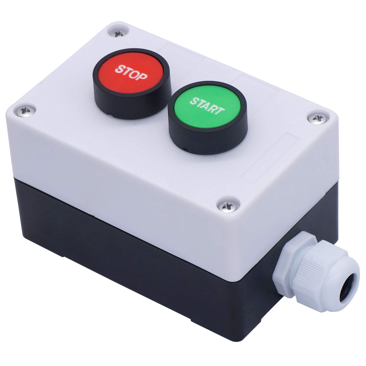
Figure 4.7-1. Push-button set 2: Taiss START/STOP station box
What It Is
A push-button station is an enclosed box that holds one or more push buttons. The wires exit the box through a cable gland that grips the cable and seals out dust and water. In a factory, a station box is mounted next to the machine, often far from the main control panel, so the operator can start and stop the machine from their work station.
| Button | Marking | Contact | Function | Terminal Strip |
|---|---|---|---|---|
| PB3 | Green, "START" | N.O. | START | PB3:1 (single blue), PB3:2 (grey) |
| PB4 | Red, "STOP" | N.C. | STOP | PB4:1 (single blue), PB4:2 (grey) |
Specifications
| Manufacturer / Type | Taiss momentary push-button switch station |
| Buttons | 2 flush momentary buttons: green START, red STOP |
| Action | Momentary (spring return) |
| Contacts | START: 1 N.O. · STOP: 1 N.C. |
| Enclosure | Plastic box with a cable gland for the wire exit |
| Contact rating | Far above the 24 V DC coil and lamp loads on your panel |
How It Works
PB3 and PB4 work exactly like PB1 and PB2 (Section 4.6):
- PB3 (N.O.): PB3:1–PB3:2 conducts only while the green START button is held.
- PB4 (N.C.): PB4:1–PB4:2 conducts until the red STOP button is pressed, and opens only while it is held.
- Both buttons are momentary and return to their normal state as soon as you let go.
The difference is not in how the buttons work but in where they are used: set 1 represents the buttons on the main control panel, and set 2 represents a second operator station out on the machine.
Why Two Push-Button Sets? Two-Location Control
Many machines can be started and stopped from more than one place, for example, from the main panel and from a station at the far end of a conveyor. This is called multi-location (two-station) control. In the later labs you will wire both sets into one circuit:
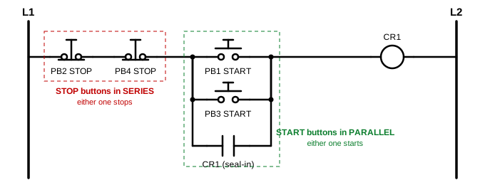
Figure 4.7-2. Two-location start/stop control
- STOP buttons (N.C.) are wired in series. Pressing either STOP button opens the rung and stops the machine. The machine can run only when both STOP buttons are released.
- START buttons (N.O.) are wired in parallel. Pressing either START button closes the rung and starts the machine.
- The seal-in contact (CR1 N.O.) is in parallel with the START buttons, so the machine keeps running after the START button is released.
Rule to remember: STOP in series, START in parallel. The same rule works for any number of stations.
Checking with a Multimeter
With the power supply unplugged, set the meter to continuity and measure at the terminal strip:
| Probes On | Button Released | Button Pressed |
|---|---|---|
| PB3:1 – PB3:2 | No beep (N.O.) | Beep |
| PB4:1 – PB4:2 | Beep (N.C.) | No beep |
If a reading is wrong, check the wires inside the station box and at the terminal strip. Because the cable runs through the gland, pulling on it can loosen a wire inside the box.
Precautions and Common Mistakes
- STOP buttons in parallel. If PB2 and PB4 are wired in parallel, pressing only one STOP button does not stop the machine, because the other one is still conducting. STOP buttons must always be in series.
- START buttons in series. If PB1 and PB3 are wired in series, the machine starts only when both are pressed simultaneously.
- Swapping PB3 and PB4. PB3 (green) is N.O. for START; PB4 (red) is N.C. for STOP.
- Pulling on the station cable. Do not carry the station box by its cable or let it hang from the cable.
- Wiring at the button instead of the terminal strip. In the labs, always connect to PB3:1, PB3:2, PB4:1, and PB4:2 on the terminal strip.
4.8 Selector Switch SSW1
Photo
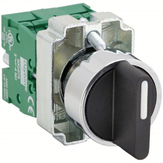 Figure 4.8-1. Front: short lever |
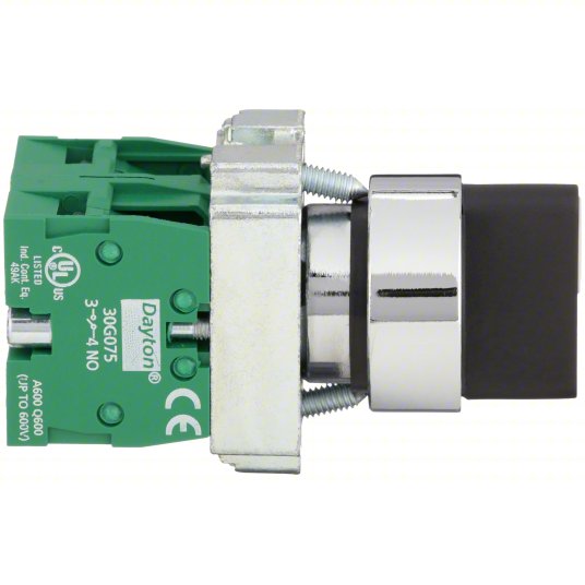 Figure 4.8-2. Side: two contact blocks |
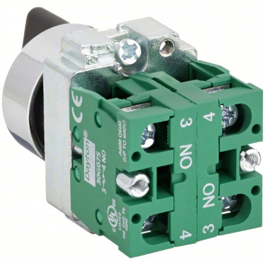 Figure 4.8-3. Back: terminals 3 and 4 |
What It Is
A selector switch is operated by turning a lever or knob instead of pressing a button. SSW1 is a 3-position selector switch with a short lever: LEFT, CENTER (OFF), and RIGHT. Behind the panel, two green contact blocks are clipped onto the switch. One closes when the lever is turned left (SWL), and the other when it is turned right (SWR).
In industry, selector switches are used wherever the operator chooses a mode or a direction: HAND–OFF–AUTO pump control, FORWARD–OFF–REVERSE for a conveyor or hoist, or selecting which of two machines to run.
Specifications
| Selector switch | Dayton 30G261 |
| Mounting size | 22 mm panel hole |
| Operator | Short lever, non-illuminated |
| Positions | 3: LEFT – CENTER (OFF) – RIGHT |
| Action | Momentary – Maintained – Momentary (LEFT and RIGHT spring back to CENTER) |
| Contacts | 2 N.O., provided by two Dayton 30G075 N.O. contact blocks |
| Contact block terminals | 3 and 4 (marked "3 NO 4" on each block) |
| Contact rating | Far above the 24 V DC lamp and coil loads on your panel |
How It Works
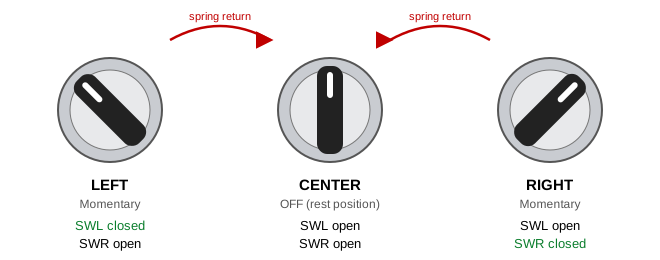
Figure 4.8-4. SSW1 positions and contact states
- Turning the lever rotates a cam inside the switch. The cam pushes the plunger of one contact block, closing that block's N.O. contact.
- CENTER (OFF) is the only position the lever stays in on its own. Both contacts are open.
- LEFT closes SWL only while you hold the lever to the left. When you let go, a spring returns the lever to CENTER, and SWL opens again.
- RIGHT works the same way for SWR.
- SWL and SWR cannot be closed simultaneously. This makes SSW1 useful for choosing between two actions that cannot occur simultaneously, such as FORWARD and REVERSE.
Because both end positions are momentary, SSW1 behaves like two N.O. push buttons that cannot be pressed together. To keep a circuit running after the lever returns to CENTER, use a seal-in contact, just as with a START push button.
Contact Table
| Contact | Terminal Strip | LEFT (held) | CENTER (OFF) | RIGHT (held) |
|---|---|---|---|---|
| SWL (N.O.) | SWL:1, SWL:2 | Closed | Open | Open |
| SWR (N.O.) | SWR:1, SWR:2 | Open | Open | Closed |
Terminals 3 and 4 of each contact block are pre-wired to the terminal strip: SWL:1 and SWR:1 on single blue terminals, SWL:2 and SWR:2 on grey terminals (Section 4.3). In the labs, always connect to the terminal strip, not to the contact blocks.
Ladder Diagram Symbol
Figure 4.8-5. SSW1 in a ladder diagram, with its target table
A selector switch is drawn with its individual contacts joined by a dashed line indicating "operated by the same lever." The target table next to it shows which contact is closed (X) in each position. In a ladder diagram, SWL and SWR usually appear in different rungs.
Checking with a Multimeter
With the power supply unplugged, set the meter to continuity and measure at the terminal strip:
| Probes On | LEFT (held) | CENTER | RIGHT (held) |
|---|---|---|---|
| SWL:1 – SWL:2 | Beep | No beep | No beep |
| SWR:1 – SWR:2 | No beep | No beep | Beep |
If SWL and SWR are swapped (SWR beeps when the lever is turned left), the two contact blocks are wired to the wrong terminals. Report it to the instructor.
Precautions and Common Mistakes
- Expecting the lever to stay. LEFT and RIGHT are momentary. If your circuit stops when you release the lever, you need a seal-in contact.
- Confusing SWL and SWR. Check the contact table before you wire. SWL is LEFT, SWR is RIGHT.
- Forcing the lever. Turn the lever only until it stops. Forcing it past the end position can break the cam.
- Loose contact blocks. The contact blocks are held by a clip on the mounting base. If a block is loose, its plunger may not reach the cam, and the contact will not close.
Output Devices (4.9)
Output Devices (4.9)
Output devices show the result of the control logic. On an industrial machine, the outputs are motors, valves, heaters, and horns. On your training panel, the pilot lamps stand in for those outputs: when a lamp turns on, imagine the conveyor motor starting or the warning horn sounding.
4.9 Pilot Lamps (R1, G1, R2, G2)
Photo
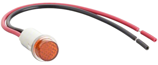 Figure 4.9-1. R1, R2: Dayton 22NY46 |
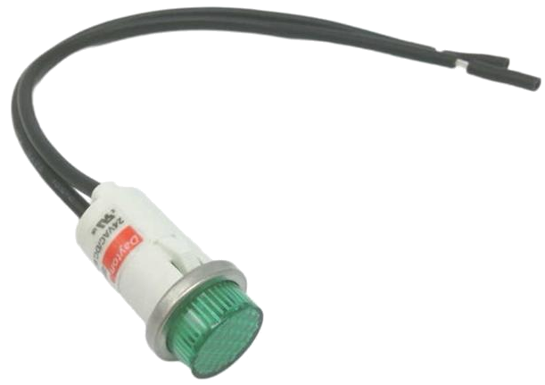 Figure 4.9-2. G1, G2: Dayton 22NY45 (green) |
What It Is
A pilot lamp (also called an indicator light) shows the operator what the machine is doing. By industry convention, green usually means "running" or "safe to proceed," and red means "stopped," "fault," or "warning." Your panel has four LED pilot lamps: R1 and R2, and G1 and G2 (green).
Note: R1 and R2 have an amber lens. In this course, they are used as red indicators (stopped, fault, or warning) and are always referred to as R1 and R2 in ladder diagrams and wiring tables.
Specifications
| R1, R2 | G1, G2 | |
|---|---|---|
| Model | Dayton 22NY46 | Dayton 22NY45 (or IDEC IL4E-24C-G-U6) |
| Lens color | Amber | Green |
| Lamp type | LED, raised head | |
| Rated voltage | 24 V AC/DC | |
| Current | About 12 mA | |
| Mounting | 12 mm panel hole | |
| Termination | 6 in wire leads | |
| Rated life | 25,000 hours | |
What the numbers mean for you: each lamp draws only about 12 mA, so all four lamps together draw less than 50 mA from the 24 V supply. The LED will last far longer than this course: 25,000 hours is almost three years of continuous operation.
How It Works
- Inside the lamp housing is an LED with a built-in current-limiting circuit, so the lamp can be connected directly to 24 V without an extra resistor.
- The lamp is rated for 24 V AC or DC. It lights whenever 24 V appears between its two leads.
- A lamp is a load, just like a relay coil. In a ladder diagram, it is always the last element on the right side of a rung, connected directly to L2.
Terminals and Wiring
The lamps are pre-wired to the pilot-lamp terminal strip on the right (4 in) rail when the panel is built (Figure 4.3-5):
- Both lamp leads are connected to the right-side clamps of the lamp's two terminals. Where a lamp has a red lead, the red lead goes to :1 (+) and the black lead to :2 (−).
- Every :2 terminal is also pre-wired to L2 with a black wire on the right side, next to the lamp lead.
In the labs, you therefore make only one connection per lamp: a wire from the contact that controls the lamp to the left-side clamp of its :1 terminal. You never add a wire to a :2 terminal.
| Lamp | + Terminal (single blue) | − Terminal (grey) |
|---|---|---|
| R1 | R1:1 ← your lab wire (left clamp) | R1:2, pre-wired to L2 |
| G1 | G1:1 ← your lab wire (left clamp) | G1:2, pre-wired to L2 |
| R2 | R2:1 ← your lab wire (left clamp) | R2:2, pre-wired to L2 |
| G2 | G2:1 ← your lab wire (left clamp) | G2:2, pre-wired to L2 |
Ladder Diagram Symbol and Example
|
A pilot lamp is drawn as a circle with rays. The letter inside shows the color: R for R1/R2, G for G1/G2. |
Figure 4.9-3. Pressing PB1 turns on G1 (the same example as Figure 3-2)
Checking a Lamp
A multimeter cannot easily test an LED lamp with a built-in current limiter, so test it with power instead. Because the :2 terminal is already connected to L2, one wire is enough. With the power supply unplugged, wire:
- L1 → G1:1 (left clamp)
After instructor approval, plug in the power supply. G1 should light. Unplug, then move the wire to R1:1, R2:1, and G2:1 in turn. If all four lamps stay dark, check the L2 bonding wire between the bottom rail and the lamp rail (Section 4.5). If only one lamp stays dark, check its pre-wired leads and its :2-to-L2 wire.
Precautions and Common Mistakes
- A lamp in series with a coil. Every lamp needs its own full 24 V. Never wire a lamp in series with a relay coil or another lamp. To show that a relay is on, use one of the relay's N.O. contacts to turn on the lamp in a separate rung.
- Adding a wire to a :2 terminal. Every :2 terminal is already L2. A lab wire on :2 is not needed, and a wire from L1 or L3 to a :2 terminal is a direct short circuit.
- Using the right-side clamps. The right-side clamps hold the lamp leads. Connect your lab wires to the left-side clamp of :1 only.
- Pulling on the lamp leads. The thin leads can break inside the lamp body. Do not use them to hold or move the lamp.
Control Relays (4.10 – 4.12)
Control relays are the decision-makers in a relay control circuit. A small current through a relay coil switches several separate contacts at the same time, so one command can hold a circuit on, lock out another circuit, and turn on a lamp all at once. The relays plug into socket bases on the top (12 in) rail; you always wire to the socket base terminals, never to the relay itself.
4.10 Relay and Timer Socket Bases
Photo
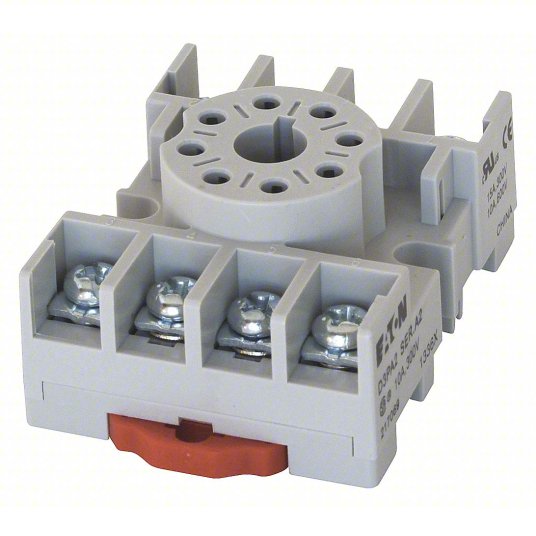 Figure 4.10-1. 8-pin socket (Dayton 5X852N) |
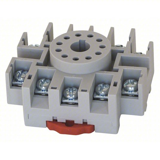 Figure 4.10-2. 11-pin socket (Dayton 6X156N) |
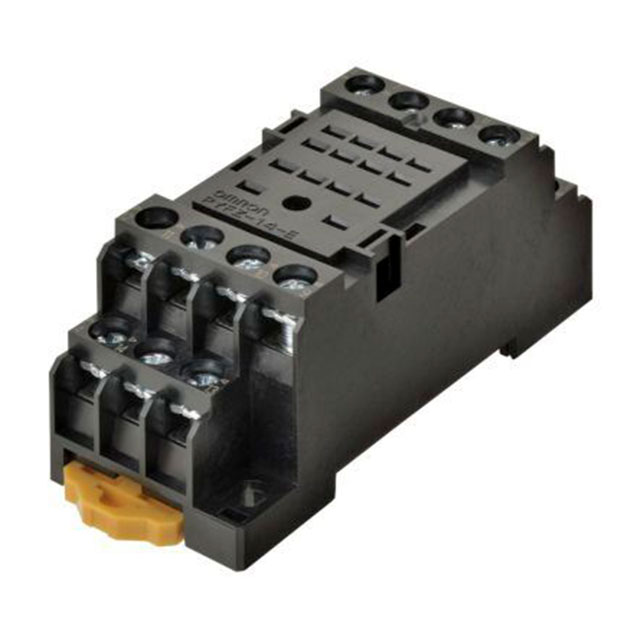 Figure 4.10-3. 14-pin socket (PYF14A) |
What It Is
A socket base is the part of a plug-in relay or timer that stays on the DIN rail. The socket has a screw terminal for every pin of the device. You wire the socket once, and the relay or timer simply plugs in. If a relay fails, a technician pulls it out and plugs in a new one in seconds, without touching a single wire. This is why plug-in relays are used in so many industrial panels.
On your panel, all six socket bases are snapped onto the top (12 in) rail, in this order from left to right: CR1, CR2, TR1, TR2, TR3, TR4.
Specifications
| Socket | Model | Qty | Used For | Rating |
|---|---|---|---|---|
| 8-pin octal | Dayton 5X852N (or compatible) | 3 | CR1, TR1, TR3 | 15 A at 300 V / 10 A at 600 V |
| 11-pin octal | Dayton 6X156N or NTE R95-114 (or compatible) | 2 | TR2, TR4 | 15 A at 300 V |
| 14-pin (MY4 type) | PYF14A (or compatible) | 1 | CR2 | Matched to the MY4 relay |
All sockets mount on a 35 mm DIN rail and use screw terminals. Every rating is far above the 24 V DC, low-current signals on your panel.
How It Works
- Inside the socket, each pin opening holds a spring contact. When the device is plugged in, each pin is gripped by its contact.
- Each spring contact is connected to one screw terminal on the outside of the socket.
- The number printed next to each screw terminal matches the device pin number. Socket terminal 3 connects to pin 3 of the relay, socket terminal 7 connects to pin 7, and so on. The pin tables in Sections 4.11 to 4.17, therefore, apply directly to the socket terminals.
Tip: The screw terminals are not arranged in number order around the socket. Always read the number printed next to each screw before you connect a wire. Never count terminals to find a number.
Which Device Goes in Which Socket
| Device | Socket | Coil Terminals (+ / −) |
|---|---|---|
| CR1 (Omron MKS2PIN) | 8-pin | 2 / 7 |
| CR2 (RONE HH54PL / MY4) | 14-pin | 14 / 13 |
| TR1 (Dayton 24EP09, On-Delay) | 8-pin | 2 / 7 |
| TR2 (Dayton 24EN86, Off-Delay) | 11-pin | 2 / 10 |
| TR3 (Dayton 24EN71, Interval-On) | 8-pin | 2 / 7 |
| TR4 (Dayton 5DRA3A, Multi-Function) | 11-pin | 2 / 10 |
In every lab, the coil + terminal is wired with an orange wire and the coil − terminal with a black wire to L2 (Section 4.1).
Plugging In and Removing a Device
- Unplug the power supply. Never plug in or pull out a relay or timer while the panel is powered.
- Octal (8-pin and 11-pin) devices: the center post has a key (a raised rib). Turn the device until the key lines up with the slot in the socket's center hole.
- 14-pin (MY4) device: the pins are arranged so the relay fits only one way. Line up the pins with the openings before pressing.
- Press the device straight down until it is fully seated. Do not rock it or force it at an angle.
- To remove: grip the device body and pull it straight up, rocking it gently from side to side if it is tight. Never pry it out with a screwdriver.
Connecting a Wire to a Socket Terminal
- Unplug the power supply.
- Strip about 5/16 in (8 mm) of the 18 AWG solid wire.
- Using the Klein Tools 7314 (#1 combo tip), loosen the terminal screw until the pressure plate is open.
- Insert the bare copper under the pressure plate, not under the screw head.
- Tighten firmly and tug the wire. It must not move.
Screwdriver: the socket terminals use combination-head screws. Always use the Klein Tools 7314. The small Klein 32581 bits do not fit these screw heads and will strip them.
Checking with a Multimeter
With the power supply unplugged and the device plugged in, set the meter to continuity:
| Probes On | Expected Reading |
|---|---|
| CR1 socket terminals 1 – 4 (N.C.) | Beep: the relay is seated, and the contact reaches the socket terminal |
| CR1 socket terminals 1 – 3 (N.O.) | No beep |
If an N.C. contact does not beep, the device is probably not fully seated. Unplug the power supply, press the device firmly into the socket, and measure again.
Precautions and Common Mistakes
- Counting terminals instead of reading numbers. Socket terminals are not in numerical order. Read the printed number every time.
- Wrong device in the socket. TR1 and TR3 use the same 8-pin socket as CR1, and TR2 and TR4 use the same 11-pin socket. A timer plugged into the wrong position will make every circuit that uses it behave incorrectly. The sockets are not labeled; follow the panel layout. From left to right on the top rail, the order is CR1, CR2, TR1, TR2, TR3, TR4.
- Timer trigger terminals. On the 11-pin sockets of TR2 and TR4, terminals 5 and 6 are the trigger input. Never connect them to L1, L2, or L3 (Section 2.4).
- Wire under the screw head. The wire must go under the pressure plate. A wire wrapped under the screw head can work loose.
- Plugging or unplugging with power on. This can arc the pins and damage the socket contacts.
4.11 CR1: Omron MKS2PIN
Photo
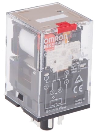
Figure 4.11-1. CR1: Omron MKS2PIN AC24 relay
What It Is
CR1 is a general-purpose power relay with an 8-pin round (octal) base. It has two contact sets, CR1A and CR1B. This contact form is called DPDT (Double Pole, Double Throw):
- Double Pole: two separate contact sets that switch at the same time.
- Double Throw: each set has a common pin that connects to either the N.O. or N.C. pin.
The model name tells you its features:
| MKS | 2 | P | I | N | AC24 |
|---|---|---|---|---|---|
| Series | 2 poles (DPDT) | Plug-in terminals | Mechanical indicator and lockable test button | LED indicator | 24 V AC coil |
Note: CR1 has a 24 V AC coil, but on your panel, it is operated from the 24 V DC supply. It works reliably, but the coil gets warm when it remains energized for extended periods. See Why CR1 Gets Warm below.
Specifications (from the Omron MKS datasheet, AC24 model)
| Coil (rated for 24 V AC) | |
| Rated voltage | 24 V AC |
| Rated current (on AC) | 96.3 mA at 60 Hz (110 mA at 50 Hz) |
| Coil resistance | 48.4 Ω |
| Must-operate voltage | 80% of rated voltage max. |
| Must-release voltage | 30% of rated voltage min. at 60 Hz |
| Power consumption (on AC) | Approx. 2.3 VA at 60 Hz |
| Current on your panel (24 V DC) | About 0.5 A (24 V ÷ 48.4 Ω), about 12 W |
| Contacts | |
| Rated load, resistive | N.O.: 10 A at 250 V AC / 10 A at 30 V DC N.C.: 5 A at 250 V AC / 5 A at 30 V DC |
| Rated load, inductive (motors, solenoids) | N.O.: 7 A at 250 V AC |
| Contact resistance | 100 mΩ max. |
| Minimum load | 10 mA at 1 V DC |
| Timing and Life | |
| Operate time/release time | 20 ms max. / 20 ms max. (AC coil) |
| Mechanical life | 5,000,000 operations min. |
| Electrical life | 100,000 operations min. (at rated load) |
| Insulation and Environment | |
| Dielectric strength | 2,500 V AC for 1 min between coil and contacts |
| Operating temperature | −25 to 60 °C for LED models |
Why CR1 Gets Warm
An AC relay coil is designed to work with alternating current. When AC flows through a coil, the coil's inductance opposes the changing current. This opposition, called inductive reactance, limits the coil current to about 96 mA, even though the copper wire itself has only 48.4 Ω of resistance.
With DC, the current does not change, so there is no inductive reactance. Only the wire resistance limits the current:
I = V ÷ R = 24 V ÷ 48.4 Ω ≈ 0.5 A P = V × I ≈ 24 V × 0.5 A ≈ 12 W
That is about five times the current and the power the coil sees on AC. The extra power turns into heat, so the relay body becomes warm, and eventually hot, if the coil stays energized for a long time. This is a good example of why the coil voltage and type (AC or DC) printed on a relay must match the control circuit in real equipment.
- Do not leave CR1 energized longer than needed. Turn the circuit off (or unplug the power supply) when you finish testing.
- Do not touch the relay cover after it has been energized for an extended period.
- If CR1 gets too hot to touch, unplug the power supply and tell the instructor.
Key Points from the Datasheet
- N.C. contacts are rated at half the current of N.O. contacts (5 A vs. 10 A). In industry, a heavy load is always switched with an N.O. contact.
- Inductive loads reduce the rating (7 A instead of 10 A), because a motor or solenoid causes an arc when the contact opens.
- Electrical life is 50 times shorter than mechanical life. The contacts wear out from arcing, not from moving. The small 24 V lamp and coil loads on your panel are very gentle on the contacts.
- The coil and the contacts are isolated by 2,500 V AC. This is what lets a 24 V control circuit safely switch a 120 V or 240 V load in a real machine.
- Mounting direction. Omron recommends mounting the relay with the side that has the printed wiring diagram facing down.
- Test button rules (see below): use it only for testing, use an insulated tool, and make sure it is released before the circuit is powered.
How It Works
- Coil OFF (no voltage between pins 2 and 7): a spring holds the armature in its rest position. Common pin 1 is connected to pin 4 (N.C.), and common pin 8 is connected to pin 5 (N.C.).
- Coil ON (24 V between pins 2 and 7): the coil becomes an electromagnet, pulling the armature in. Both contact sets switch simultaneously: pin 1 moves to pin 3 (N.O.), and pin 8 moves to pin 6 (N.O.). The LED lights and the mechanical indicator move.
- Coil OFF again: the spring returns the armature, and all contacts return to their normal state.
The coils CR1A and CR1B are electrically isolated from one another, so they can be used in two completely different rungs.
Pin Diagram
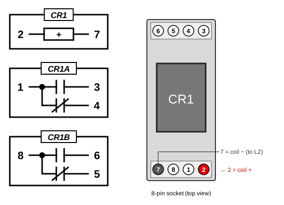
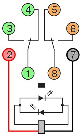
Figure 4.11-2. CR1 pin diagram (coil de-energized) and 8-pin socket terminal layout. In the drawing, terminal 2 (coil +) is shown in red and terminal 7 (coil −) in dark grey; the real socket has no color marks.
Contact Table
| Function | Pins | a (Common) | b (N.O.) | c (N.C.) | Written As |
|---|---|---|---|---|---|
| Coil | 2 – 7 | Pin 2 = coil + (orange wire), pin 7 = coil − (black wire to L2) | CR1:2, CR1:7 | ||
| Contact set CR1A | 1, 3, 4 | 1 | 3 | 4 | N.O. = CR1:1-3 N.C. = CR1:1-4 |
| Contact set CR1B | 8, 6, 5 | 8 | 6 | 5 | N.O. = CR1:8-6 N.C. = CR1:8-5 |
Memory tip: the two contact sets are mirror images. CR1A uses pins 1-3-4, and CR1B uses 8-6-5 (subtract each CR1A pin number from 9). The coil uses the two pins left over, 2 and 7, which are the two outer terminals of the socket's bottom row.
Coil polarity: the AC coil itself does not care which way DC is applied, but always wire pin 2 as + and pin 7 as − so that every relay and timer on the panel follows the same rule.
Screwdriver: tighten the CR1 socket terminals with the Klein Tools 7314 (#1 combo tip). The small Klein 32581 bits do not fit these screw heads and will strip them.
Lockable Test Button
The MKS2PIN has a two-way test button on the front of the cover, with a red latching lever (red identifies the AC-coil version). The test button moves the contacts by hand without energizing the coil, allowing a technician to test the circuit that the relay controls.
| Mode | How | Result |
|---|---|---|
| Normal operation | Latching lever in the normal position | Contacts are operated only by the coil. |
| Momentary test | Slide the latching lever to the first position, then press the button with an insulated tool | Contacts switch only while the button is pressed. |
| Locked test | Slide the latching lever to the second position | Contacts stay switched until the lever is returned. |
In this course, never use the test button. Before every lab, check that the latching lever is in the normal position. A relay left in the locked test position behaves as if its coil were always ON, and your circuit will not work correctly. Omron also warns that pulling the button too hard can skip the momentary position and go straight to the locked position.
Typical Uses in This Course
- Seal-in (holding) contact: a CR1 N.O. contact wired in parallel with the START button keeps the relay energized after the button is released.
- Master control relay (MCR): a CR1 N.O. contact feeds the controlled bus L3.
- Status lamps: the N.O. side of one set lights a green RUN lamp while the N.C. side lights a red STOP lamp.
- Dry contact for a timer trigger: a CR1 contact wired directly across TR2 or TR4 terminals 5 and 6 (for example, CR1:8 → TR2:5 and CR1:6 → TR2:6).
Because CR1 has only two contact sets, a circuit that requires more than two contacts from the same relay should use CR2, which has four contact sets (Section 4.12).
Checking CR1 with a Multimeter
With the power supply unplugged and CR1 plugged into its socket, measure at the socket terminals:
| # | Meter Setting | Probes On | Expected Reading |
|---|---|---|---|
| 1 | Continuity | 1 – 4 | Beep (N.C. closed) |
| 2 | Continuity | 1 – 3 | No beep (N.O. open) |
| 3 | Continuity | 8 – 5 | Beep (N.C. closed) |
| 4 | Continuity | 8 – 6 | No beep (N.O. open) |
| 5 | Continuity | 1 – 8 | No beep (the two sets are isolated) |
| 6 | Resistance (Ω) | 2 – 7 | About 48 Ω (the coil resistance). The LED circuit can slightly affect the reading. |
If checks 2 or 4 beep, the test button is probably locked. Return the latching lever to the normal position.
Then test the relay with power. With the power supply unplugged, wire:
- L1 → CR1:2 (orange) and CR1:7 → L2 (black): energizes the coil
- L1 → CR1:1 and CR1:3 → G1:1: lights G1 through the CR1A N.O. contact (G1:2 is already connected to L2)
After instructor approval, plug in the power supply. You should hear a click, the LED and the mechanical indicator should show that the relay is operated, and G1 should light. Unplug, move the wire from CR1:3 to CR1:4 (N.C.), and repeat: G1 should now stay off while the coil is energized. Keep each test short because the coil heats up while energized.
Precautions and Common Mistakes
- Leaving CR1 energized. On 24 V DC, the AC coil draws about 0.5 A and gets warm. Do not leave a circuit running unattended.
- Test button left locked. Check the latching lever before every lab. Never use the test button to "help" a circuit work.
- Mixing pins from two contact sets. A contact is always the common pin plus one pin from the same set. Pins 1 and 6, for example, are not a contact: they belong to different sets and never connect.
- Using N.C. when N.O. is needed. Pins 1-3 and 1-4 are easy to swap. Always check your wiring table against the contact table above.
- Counting socket terminals. The socket terminals are not numbered (Figure 4.11-2). Read the number next to each screw.
- Relay not fully seated. Line up the key on the center post and push the relay straight down until it is fully seated (Section 4.10).
4.12 CR2: RONE HH54PL (MY4 Type)
Photo
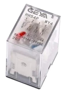
Figure 4.12-1. CR2: RONE HH54PL DC24V relay (MY4 type)
What It Is
CR2 is a miniature control relay with a 14-pin plug-in base. It has four contact sets, CR2A, CR2B, CR2C, and CR2D. This contact form is called 4PDT (four-pole, double-throw). The HH54P is the same size and pin layout as the widely used MY4 relay, so relays and sockets of this type are interchangeable between many manufacturers.
The model name tells you its features:
| HH | 54 | P | L | DC24V |
|---|---|---|---|---|
| Miniature control relay | 4PDT (4 contact sets) | Plug-in terminals | LED operating indicator | 24 V DC coil |
CR1 or CR2?
| CR1 (MKS2PIN) | CR2 (HH54PL) | |
|---|---|---|
| Contact sets | 2 (DPDT) | 4 (4PDT) |
| Contact rating | 10 A (N.O.) | 3 A |
| Coil on your panel | 24 V AC coil on 24 V DC: about 0.5 A, gets warm | 24 V DC coil: 37 mA, stays cool |
| Base | 8-pin octal | 14-pin (MY4 type) |
| Best used when | A heavier load must be switched | One command must control many circuits |
Specifications (from the HH52/HH53/HH54 series datasheet, HH54P-LC DC24V)
| Coil | |
| Rated voltage | 24 V DC |
| Rated current | 37 mA |
| Coil resistance | 650 Ω |
| Power consumption | Approx. 0.9 W |
| Operating (pick-up) voltage | 75% of rated voltage (18 V) at 20 °C |
| Reset (drop-out) voltage | 10% of rated voltage (2.4 V) at 20 °C |
| Maximum continuous voltage | 110% of rated voltage (26.4 V) |
| Operating indicator | LED, green for DC coils, on while the coil is energized |
| Contacts | |
| Rated thermal current | 3 A per contact |
| Rated load, resistive | 3 A at 240 V AC / 3 A at 30 V DC |
| Rated load, inductive | 0.3 A at 220 V AC / 0.2 A at 110 V DC |
| Contact resistance | 50 mΩ max. (new) |
| Minimum load | 5 V, 1 mA |
| Timing and Life | |
| Operate time/reset time | 20 ms max. / 20 ms max. |
| Mechanical life | 100 million operations (DC coil) |
| Insulation and Environment | |
| Dielectric strength | 2,000 V AC for 1 min between coil and contacts |
| Operating temperature | −25 to +60 °C |
Key Points from the Datasheet
- Low coil current. The DC24V coil draws only 37 mA (0.9 W). CR2 can remain energized for extended periods without overheating, unlike CR1.
- The coil picks up at 18 V (75% of 24 V) and drops out below 2.4 V (10% of 24 V). A loose connection that makes the voltage sag can make CR2 chatter or fail to pick up.
- Do not exceed 26.4 V (110%) continuously on the coil.
- Lower contact rating than CR1. Each CR2 contact is rated 3 A resistive, and much less for inductive loads (0.3 A at 220 V AC). In industry, a relay like CR2 switches signals and other relay coils, not motors.
- The LED is polarity-sensitive. Pin 14 is coil + and pin 13 is coil −. Reversed, the green LED will not light.
- Very long mechanical life (100 million operations). Contact wear from the small 24 V signals on your panel is negligible.
How It Works
- Coil OFF (no voltage between pins 14 and 13): each common pin rests on its N.C. pin: 9–1, 10–2, 11–3, and 12–4.
- Coil ON (24 V between pins 14 and 13): the armature pulls in, and all four contact sets switch at the same time, within 20 ms: 9–5, 10–6, 11–7, and 12–8 close. The green LED lights.
- Coil OFF again: all four sets return to their N.C. positions within 20 ms.
The coil and the four contact sets are electrically isolated from one another, so each contact set can be used in a different rung.
Pin Diagram
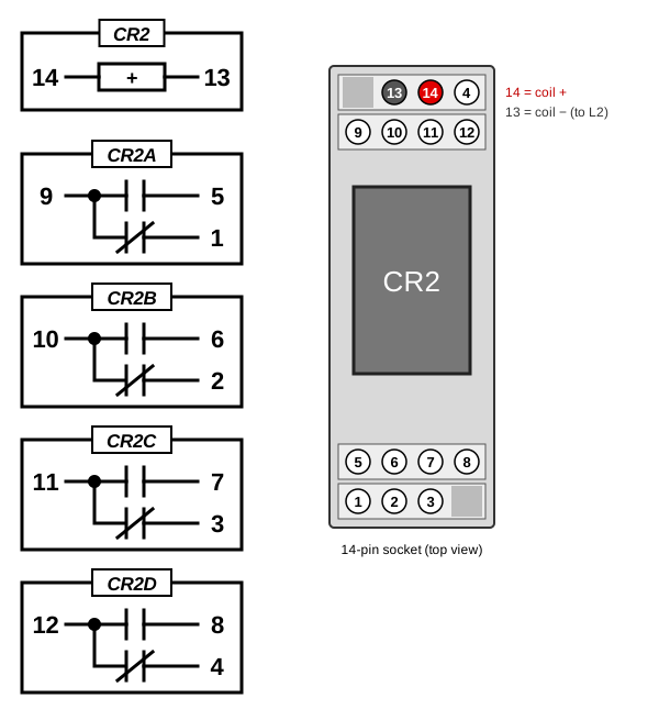
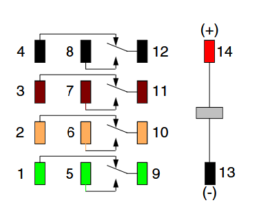
Figure 4.12-2. CR2 pin diagram (coil de-energized) and 14-pin socket terminal layout. In the drawing, terminal 14 (coil +) is shown in red and terminal 13 (coil −) in dark grey; the real socket has no color marks.
Contact Table
| Function | Pins | a (Common) | b (N.O.) | c (N.C.) | Written As |
|---|---|---|---|---|---|
| Coil | 14 – 13 | Pin 14 = coil + (orange wire), pin 13 = coil − (black wire to L2) | CR2:14, CR2:13 | ||
| Contact set CR2A | 9, 5, 1 | 9 | 5 | 1 | N.O. = CR2:9-5 N.C. = CR2:9-1 |
| Contact set CR2B | 10, 6, 2 | 10 | 6 | 2 | N.O. = CR2:10-6 N.C. = CR2:10-2 |
| Contact set CR2C | 11, 7, 3 | 11 | 7 | 3 | N.O. = CR2:11-7 N.C. = CR2:11-3 |
| Contact set CR2D | 12, 8, 4 | 12 | 8 | 4 | N.O. = CR2:12-8 N.C. = CR2:12-4 |
Memory tip: each contact set is a group of three pin numbers that differ by 4. The common is in the 9–12 row, the N.O. pin is 4 less (5–8), and the N.C. pin is 8 less (1–4). For example, CR2C: common 11, N.O. 11 − 4 = 7, N.C. 11 − 8 = 3. The coil uses the last two numbers, 14 (+) and 13 (−).
Screwdriver: tighten the CR2 socket terminals with the Klein Tools 7314 (#1 combo tip). The small Klein 32581 bits do not fit these screw heads and will strip them.
Typical Uses in This Course
- One command, many actions: a single CR2 coil can seal itself in (CR2A), interlock another relay (CR2B), turn on a RUN lamp (CR2C), and turn off a STOP lamp (CR2D) at the same time.
- Interlocking: a CR2 N.C. contact in series with another relay's coil prevents both from being ON together, for example, FORWARD and REVERSE.
- Sequencing with timers: CR2 contacts start timers, feed L3, or pass a signal from one stage of a sequence to the next.
Checking CR2 with a Multimeter
With the power supply unplugged and CR2 plugged into its socket, measure at the socket terminals:
| # | Meter Setting | Probes On | Expected Reading |
|---|---|---|---|
| 1 | Continuity | 9 – 1, 10 – 2, 11 – 3, 12 – 4 | Beep on each (N.C. closed) |
| 2 | Continuity | 9 – 5, 10 – 6, 11 – 7, 12 – 8 | No beep on each (N.O. open) |
| 3 | Continuity | 9 – 10 | No beep (the sets are isolated) |
| 4 | Resistance (Ω) | 14 – 13 | About 650 Ω (the coil). The LED circuit can change the reading slightly depending on probe polarity. |
Then test the relay with power. With the power supply unplugged, wire:
- L1 → CR2:14 (orange) and CR2:13 → L2 (black): energizes the coil
- L1 → CR2:9 and CR2:5 → G1:1: lights G1 through the CR2A N.O. contact (G1:2 is already connected to L2)
After instructor approval, plug in the power supply. You should hear a click, the green LED on CR2 should light, and G1 should light. Unplug, move the two contact wires to the next set (10 and 6, then 11 and 7, then 12 and 8), and repeat to check all four N.O. contacts.
Precautions and Common Mistakes
- Coil wired backward. Pin 14 is +, pin 13 is −. With the polarity reversed, the LED does not light, which makes troubleshooting confusing.
- Mixing pins from two contact sets. A contact is always the common (9–12) plus a pin from the same set. Pins 9 and 6, for example, belong to different sets and never connect.
- Confusing N.O. and N.C. The N.O. pins are 5–8, and the N.C. pins are 1–4. On the socket, terminal 4 is in the top row, away from 1–3, so always read the number. Check the contact table every time.
- Counting socket terminals. The terminals are not in number order (Figure 4.12-2). Read the number next to each screw.
- Forcing the relay into the socket. The 14 pins fit only one way. Line them up before pressing straight down (Section 4.10).
- Using CR2 for heavy loads. On a real machine, switch motors and heaters with a contactor or a relay rated for the load, not with CR2's 3 A contacts.
Timer Relays (4.13 – 4.17)
Timer relays add <strong>time</strong> to relay logic: they delay a start, delay a stop, or keep an output on for a set time. Real machines use them for start-up warning horns, cooling-fan run-on, timed filling, and motor sequencing. Section 4.13 explains the ideas shared by all timers; Sections 4.14-4.17 describe TR1-TR4.
4.13 Timer Relay Basics
What Is a Timer Relay?
A timer relay (time delay relay) is a relay with a built-in electronic timer. Like a control relay, it has output contacts that switch other circuits. The difference is when the contacts switch: instead of switching the instant the coil is energized, a timer relay switches its contacts after a preset time, or for a preset time, depending on its function.
Timer relays are everywhere in industry: a horn sounds for 10 seconds before a conveyor starts, a cooling fan keeps running for 2 minutes after a motor stops, a pump fills a tank for exactly 30 seconds, or a warning light flashes while a machine is in a fault condition.
The Four Timer Relays on Your Panel
| Timer | Model | Function | Pins | Time Range | Setting | Trigger 5-6 |
|---|---|---|---|---|---|---|
| TR1 | Dayton 24EP09 | On-Delay | 8 | 0.6 – 60 s | Knob | No |
| TR2 | Dayton 24EN86 | Off-Delay | 11 | 0.6 – 60 s | Knob | Yes |
| TR3 | Dayton 24EN71 | Interval-On | 8 | 0.03 – 3 min (1.8 – 180 s) | Knob | No |
| TR4 | Dayton 5DRA3A | Multi-Function (10 functions) | 11 | 0.05 s – 999 h | Push-button thumbwheels | Yes (some functions) |
All four timers operate on 24 V AC/DC and have DPDT output contacts rated at 10 A at 240 V AC/30 V DC.
Two Inputs: Supply and Trigger
This is the most important idea in this section. A timer relay can have two different inputs, and you must know which one starts the timing.
| Input | Terminals | What It Does | How It Is Wired |
|---|---|---|---|
| Supply (often called the "coil") | 8-pin: 2 (+) and 7 (−) 11-pin: 2 (+) and 10 (−) |
Powers the timer's electronics. For TR1 and TR3, applying the supply also serves as the start signal. | + from a rung (orange wire), − to L2 (black wire), like any relay coil. |
| Trigger (control switch) | 11-pin only: 5 and 6 | Starts or controls the timing for triggered functions (TR2, TR4 functions C, D, G, H, J, K). | A dry contact (a relay contact or a button) wired directly across 5 and 6. Nothing else. |
- Supply-started timers (TR1, TR3, and TR4 functions A, B, E, F): timing begins when the supply is applied. Removing the supply resets the timer.
- Trigger-started timers (TR2 and TR4 functions C, D, G, H, J, K): the supply must stay ON at all times. The trigger contact across 5-6 starts and controls the timing. If the supply is removed, the timer cannot time, and the output drops out immediately.
The trigger must be a dry contact. The Macromatic instructions for the TD-7 timer (the design behind TR4) state: "This Trigger must be a dry-type contact (applying voltage to the pins could damage the unit)." Never connect terminal 5 or 6 to L1, L2, L3, or any other wire. Wire only the two terminals of one contact to them, for example, CR1:8 → TR2:5 and CR1:6 → TR2:6.
The Output Contacts
Every timer on your panel has two contact sets that follow the same a–b N.O. / a–c N.C. convention as the control relays (Section 3.3). Both sets always switch together; at the moment, the timer function says so.
| Base | Timers | Set A (a, b N.O., c N.C.) | Set B (a, b N.O., c N.C.) | Supply (+ / −) | Trigger |
|---|---|---|---|---|---|
| 8-pin | TR1, TR3 | 1, 3, 4 | 8, 6, 5 | 2 / 7 | None |
| 11-pin | TR2, TR4 | 1, 3, 4 | 11, 9, 8 | 2 / 10 | 5 – 6 |
These timers have no instantaneous contacts; every contact is timed. If a circuit needs a contact that switches the instant the timer is energized, use a CR1 or CR2 contact controlled by the same rung.
Timer Contact Symbols
In a ladder diagram, a timed contact is drawn as a normal contact with an arrow. The arrow shows which direction of switching is delayed.
| Symbol | Name | Behavior | Used With |
|---|---|---|---|
|
N.O.T.C. (Normally Open, Timed Closed) |
Closes after the preset time; opens immediately when the timer is reset. | On-Delay (TR1) |
|
N.C.T.O. (Normally Closed, Timed Open) |
Opens after the preset time; closes immediately when the timer is reset. | On-Delay (TR1) |
|
N.O.T.O. (Normally Open, Timed Open) |
Closes immediately when triggered; opens after the preset time once the trigger is removed. | Off-Delay (TR2) |
|
N.C.T.C. (Normally Closed, Timed Closed) |
Opens immediately when triggered; closes after the preset time once the trigger is removed. | Off-Delay (TR2) |
For interval, flasher, and other functions (TR3 and several TR4 functions), the contacts are drawn as ordinary N.O. and N.C. contacts labeled with the timer name, and the function is described in the timing diagram.
How to Read a Timing Diagram
A timing diagram shows how the inputs and outputs of a timer change over time. It is the fastest way to understand what a timer function does.
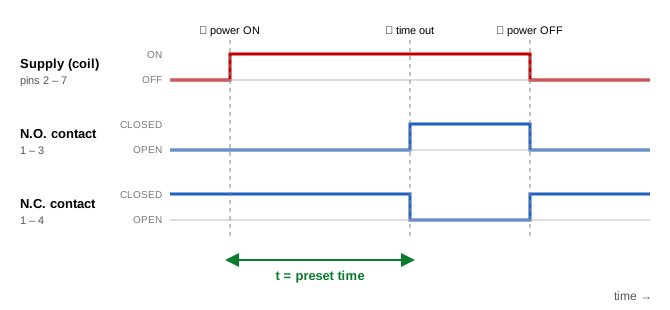
Figure 4.13-1. Example timing diagram (On-Delay)
- Time runs from left to right. Each horizontal line is one signal.
- High = ON / CLOSED, low = OFF / OPEN. For the supply and the trigger, high means voltage is applied, or the trigger contact is closed. For an output contact, high means the contact is closed.
- Read the vertical dashed lines as events. In Figure 4.13-1: at ① the supply turns on, and timing starts; at ②, one preset time t later, the N.O. contact closes, and the N.C. contact opens; at ③ the supply turns off, and both contacts return to normal immediately.
- The N.O. and N.C. contacts of the same set are always opposite. When one is high, the other is low.
Each timer tab (Sections 4.14 to 4.17) has its own timing diagram.
Setting the Time
| Timers | Method | Accuracy |
|---|---|---|
| TR1, TR2, TR3 | Turn the knob to the desired value on the printed scale (seconds for TR1 and TR2, minutes for TR3). | The scale is only approximate: about ±2% (or 50 ms) in the middle of the range, but the actual time can be up to 50% shorter at the minimum mark and up to 5% longer at the maximum mark. |
| TR4 | Select the function and the time unit with the outer push-button thumbwheels, and set a 3-digit number (001–999) with the middle thumbwheels. Time = number × unit. | Setting accuracy ±0.1% of the set time or ±50 ms, whichever is greater. |
Good practice: when a lab asks for a specific time (for example, 5 seconds), set the knob, then measure the actual delay with a stopwatch and adjust. Record the measured time, not the dial setting.
Reset
- All four timers use time-limit reset: when the supply is removed (or, for triggered functions, when the function ends), the timer returns to its starting state, ready for the next cycle.
- The timer needs a short reset time (about 0.1 s for TR4) with the supply off before it can start a new, full timing cycle. Turning the supply off and on very quickly may not reset it.
- For triggered functions, the trigger contact must stay closed for at least the minimum control pulse (0.1 s for TR4) to be recognized.
Precautions and Common Mistakes
- Voltage on the trigger terminals. Terminals 5 and 6 accept only a dry contact. Never connect them to L1, L2, L3, or any other circuit.
- Supply switched off on a triggered timer. TR2 and the triggered TR4 functions require the supply to be ON at all times. Switching the supply with the same contact that should trigger the timer is the most common timer wiring mistake.
- Trusting the dial. The knob scale is approximate. Measure the actual time.
- Changing TR4 settings while powered. The TR4 function cannot be changed while the supply is on. Unplug the power supply, set the function and time, then power up.
- Expecting an instantaneous contact. Timer contacts are all timed. Use a CR1 or CR2 contact for an instant response.
- Wrong pins on the 11-pin base. On TR2 and TR4, set B is 11-9-8, and the supply is 10, not 7 as on the 8-pin timers.
4.14 TR1: On-Delay (Dayton 24EP09)
Photo
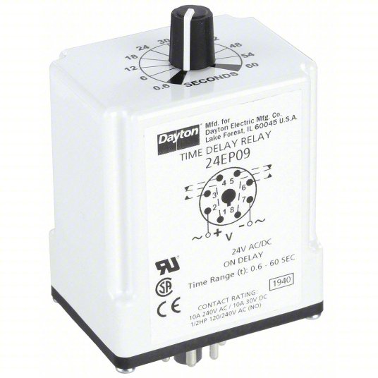 Figure 4.14-1. TR1: Dayton 24EP09 |
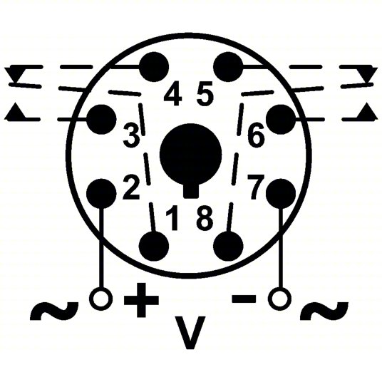 Figure 4.14-2. Wiring diagram printed on the case (bottom view of the pins) |
What It Is
TR1 is an On-Delay timer, the most common timer function in industry. When its supply is turned on, TR1 waits for the preset time, and only then do its contacts switch. When the supply is turned off, the contacts return to normal immediately.
Think of it as "delay ON, instant OFF." It is used whenever something must wait before it starts: a warning horn before a conveyor moves, a motor that starts a few seconds after another one, or a lamp that turns on only if a condition lasts longer than a set time.
Specifications
| Model | Dayton 24EP09 |
| Function | On-Delay (single function) |
| Supply voltage | 24 V AC/DC, approx. 2 VA |
| Time range | 0.6 – 60 seconds |
| Adjustment | Knob (potentiometer), scale marked in SECONDS |
| Timing accuracy | ±2% or 50 ms (middle of scale); +0 / −50% at the minimum mark; +5 / −0% at the maximum mark |
| Reset | Time-limit reset: removing the supply resets the timer |
| Contacts | DPDT, silver-nickel, 10 A at 240 V AC / 10 A at 30 V DC; 1/2 HP at 120/240 V AC (N.O.) |
| Life | Electrical 100,000 operations; mechanical 10,000,000 operations |
| Base | 8-pin octal (Section 4.10) |
How It Works
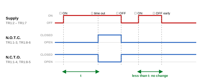
Figure 4.14-3. TR1 On-Delay timing diagram
- ① Supply ON: timing starts. The contacts do not move yet.
- ② Time out: after the preset time t, both contact sets switch. The N.O. contacts (1-3, 8-6) close, and the N.C. contacts (1-4, 8-5) open. They stay switched as long as the supply stays on.
- ③ Supply OFF: the contacts return to normal immediately, and the timer resets.
- ④–⑤ Supply ON for less than t: the timer resets before it times out, so the contacts never switch. The next time the supply is applied, timing starts again from zero.
In a ladder diagram, TR1's N.O. contacts are drawn as N.O.T.C. (normally open, timed closed) and its N.C. contacts as N.C.T.O. (normally closed, timed open) (Section 4.13).
Pin Diagram
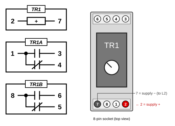
Figure 4.14-4. TR1 pin diagram and 8-pin socket terminal layout. In the drawing, terminal 2 (+) is shown in red and terminal 7 (−) in dark grey; the real socket has no color marks.
Contact Table
| Function | Pins | a (Common) | b (N.O.T.C.) | c (N.C.T.O.) | Written As |
|---|---|---|---|---|---|
| Supply | 2 – 7 | Pin 2 = + (orange wire), pin 7 = − (black wire to L2) | TR1:2, TR1:7 | ||
| Contact set TR1A | 1, 3, 4 | 1 | 3 | 4 | TR1:1-3, TR1:1-4 |
| Contact set TR1B | 8, 6, 5 | 8 | 6 | 5 | TR1:8-6, TR1:8-5 |
TR1 uses exactly the same pin numbers as CR1 (Section 4.11). The only difference is when the contacts switch.
Application Example: Conveyor Start-Up Warning
Many plants require a warning before a conveyor starts, so that nobody is touching the belt. With TR1:
- The operator presses START. A control relay seals in, turns on a warning lamp or horn, and energizes TR1.
- After the preset time (for example, 5 seconds), TR1's N.O.T.C. contact closes and starts the conveyor motor, and its N.C.T.O. contact turns the warning off.
- Pressing STOP drops out the control relay, which removes TR1's supply. The conveyor stops immediately, and TR1 is reset for the next start.
Checking TR1
With the power supply unplugged, set the knob to about 5 seconds and wire:
- L1 → TR1:2 (orange) and TR1:7 → L2 (black): supply
- L1 → TR1:1 and TR1:3 → G1:1: G1 shows the N.O.T.C. contact
- L1 → TR1:8 and TR1:5 → R1:1: R1 shows the N.C.T.O. contact
After instructor approval, plug in the power supply and start a stopwatch. R1 should be on at first; after about 5 seconds, R1 should turn off, and G1 should turn on. Unplug the power supply: G1 should turn off and R1 should turn back on immediately. Record the measured delay and compare it with the knob setting.
Precautions and Common Mistakes
- Expecting the output to stay on after the supply is removed. TR1 resets instantly when its supply goes off. If the load must stay on, the circuit needs a seal-in contact.
- Interrupting the supply during timing. Any interruption, even a short one, resets the timer to zero. A loose supply wire can make TR1 appear never to time out.
- Trusting the dial. The scale is approximate, especially near the minimum mark. Measure the actual delay.
- Confusing TR1 with CR1. TR1 and CR1 use the same pin numbers but plug into different sockets (the top rail order is CR1, CR2, TR1, TR2, TR3, TR4).
4.15 TR2: Off-Delay (Dayton 24EN86)
Photo
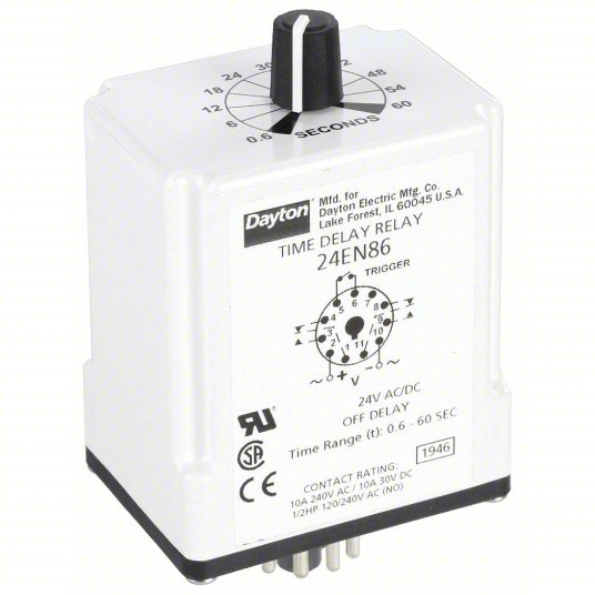 Figure 4.15-1. TR2: Dayton 24EN86 |
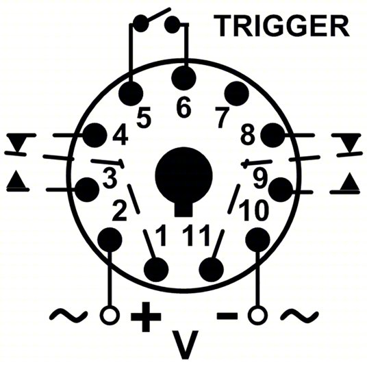 Figure 4.15-2. Wiring diagram printed on the case (bottom view of the pins) |
What It Is
TR2 is an Off-Delay timer: "instant ON, delay OFF." Its contacts switch immediately when the trigger closes, and they stay switched for the preset time after the trigger opens.
Off-delay timers keep something running for a while after the command to stop: a cooling fan that runs for 60 seconds after a motor stops, a stairway light that stays on after the switch is released, or a conveyor that keeps moving until the last part has cleared.
TR2 has two inputs. The supply (2 and 10) must be ON all the time. The trigger (5 and 6) is what controls the timing, and it must be a dry contact wired directly across 5 and 6 (Section 4.13).
Specifications
| Model | Dayton 24EN86 |
| Function | Off-Delay (single function), trigger-controlled |
| Supply voltage | 24 V AC/DC, approx. 2 VA; must stay ON |
| Trigger | Dry contact across terminals 5 and 6 |
| Time range | 0.6 – 60 seconds |
| Adjustment | Knob (potentiometer), scale marked in SECONDS |
| Timing accuracy | ±2% or 50 ms (middle of scale); +0 / −50% at the minimum mark; +5 / −0% at the maximum mark |
| Reset | Time-limit reset |
| Contacts | DPDT, silver-nickel, 10 A at 240 V AC / 10 A at 30 V DC; 1/2 HP at 120/240 V AC (N.O.) |
| Life | Electrical 100,000 operations; mechanical 10,000,000 operations |
| Base | 11-pin octal (Section 4.10) |
How It Works
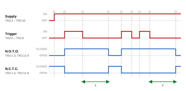
Figure 4.15-3. TR2 Off-Delay timing diagram
- ① Supply ON: TR2 is powered and ready. Nothing else happens yet.
- ② Trigger closes: the contacts switch immediately. The N.O. contacts (1-3, 11-9) close and the N.C. contacts (1-4, 11-8) open.
- ③ Trigger opens: timing starts. The contacts stay switched.
- ④ Time out: after the preset time t, the contacts return to normal.
- ⑤–⑧ Trigger re-closed during timing: the trigger closes at ⑤ and opens at ⑥, so timing starts. At ⑦, it closes again before the time is up: the timing is canceled, and the contacts simply stay switched. At ⑧, the trigger opens again, and the timing resets to zero.
- ⑨ Time out: one full time t after the last opening of the trigger, the contacts return to normal.
In a ladder diagram, TR2's N.O. contacts are drawn as N.O.T.O. (normally open, timed open) and its N.C. contacts as N.C.T.C. (normally closed, timed closed) (Section 4.13).
Wiring the Trigger
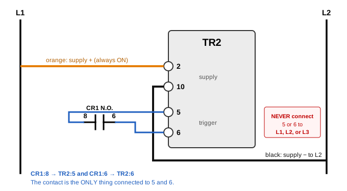
Figure 4.15-4. Wiring the TR2 supply and trigger
- The supply is wired straight from L1 (or L3) to TR2:2 and from TR2:10 to L2, so it is ON whenever the panel is powered.
- The trigger is a relay contact (or a push button) with its two terminals wired only to TR2:5 and TR2:6. In the example, CR1's N.O. contact is used: CR1:8 → TR2:5 and CR1:6 → TR2:6.
- When CR1 energizes, its contact closes the trigger, and TR2 switches immediately. When CR1 drops out, the trigger opens, and TR2 begins its off-delay.
Pin Diagram
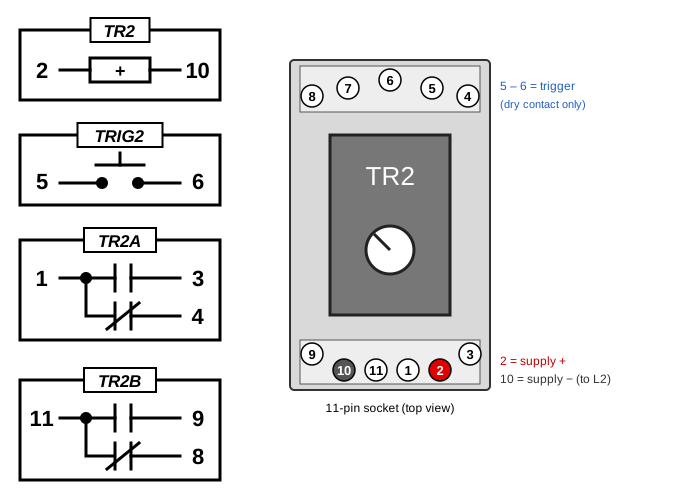
Figure 4.15-5. TR2 pin diagram and 11-pin socket terminal layout. In the drawing, terminal 2 (+) is shown in red and terminal 10 (−) in dark grey; the real socket has no color marks.
Contact Table
| Function | Pins | a (Common) | b (N.O.T.O.) | c (N.C.T.C.) | Written As |
|---|---|---|---|---|---|
| Supply | 2 – 10 | Pin 2 = + (orange wire), pin 10 = − (black wire to L2) | TR2:2, TR2:10 | ||
| Trigger | 5 – 6 | Dry contact only, wired directly across 5 and 6 | TR2:5, TR2:6 | ||
| Contact set TR2A | 1, 3, 4 | 1 | 3 | 4 | TR2:1-3, TR2:1-4 |
| Contact set TR2B | 11, 9, 8 | 11 | 9 | 8 | TR2:11-9, TR2:11-8 |
Pin 7 is not used on TR2. Set A uses the same pins as the 8-pin timers (1-3-4), but set B is 11-9-8, and the supply is 10, not 7.
Application Example: Motor Cooling Fan
- A control relay, CR1, runs a motor. A CR1 N.O. contact is wired across TR2's trigger (5-6).
- A TR2 N.O.T.O. contact runs the cooling fan. As soon as the motor starts, the fan starts too.
- When the operator presses STOP, the motor stops and CR1 drops out, opening the trigger. The fan runs for the preset time (for example, 60 seconds) and then stops automatically.
Checking TR2
With the power supply unplugged, set the knob to about 5 seconds and wire:
- L1 → TR2:2 (orange) and TR2:10 → L2 (black): supply, always ON
- PB1:1 → TR2:5 and PB1:2 → TR2:6: PB1 (N.O.) is the trigger. Do not connect PB1 to L1.
- L1 → TR2:1 and TR2:3 → G1:1: G1 shows the N.O.T.O. contact
After instructor approval, plug in the power supply. Press and hold PB1: G1 should turn on immediately. Release PB1 and start the stopwatch: G1 should stay on for about 5 seconds, then turn off. Then try pressing PB1 again before the time runs out, and watch the timer restart.
Precautions and Common Mistakes
- Voltage on 5 or 6. Never connect terminal 5 or 6 to L1, L2, L3, or any wire other than the two terminals of the trigger contact. This can damage the timer.
- Switching the supply instead of the trigger. If the supply (2) is wired through the controlling contact, TR2 loses power the moment the contact opens and drops out immediately, with no off-delay. The supply must be ON at all times.
- Using pin 7 or set B as 8-6-5. TR2 is an 11-pin timer: supply is 10, and set B is 11-9-8.
- Expecting timing to start when the trigger closes. The off-delay starts when the trigger opens.
- Trusting the dial. Measure the actual delay with a stopwatch.
4.16 TR3: Interval-On (Dayton 24EN71)
Photo
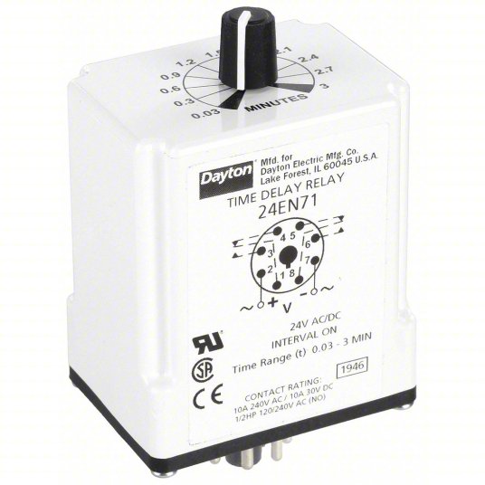 Figure 4.16-1. TR3: Dayton 24EN71 |
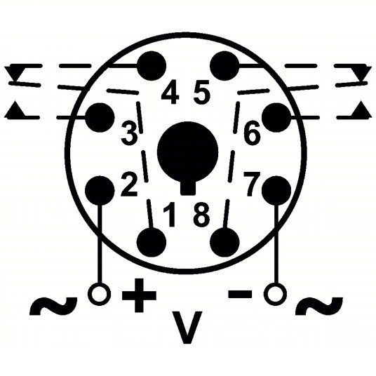 Figure 4.16-2. Wiring diagram printed on the case (bottom view of the pins) |
What It Is
TR3 is an Interval-On timer: "instant ON, timed OFF, while powered." When its supply is turned on, its contacts switch immediately and stay switched for the preset time; then they return to normal even though the supply is still on.
Interval timers are used when an output must run for a fixed duration after a start signal: a pump that fills a tank for 30 seconds, a lubrication valve that opens for 10 seconds at start-up, or a horn that sounds for a few seconds and then stops on its own.
Compare with TR1: TR1 (On-Delay) waits t, then switches. TR3 (Interval-On) switches first, then switches back after t. In both, removing the supply resets the timer.
Specifications
| Model | Dayton 24EN71 |
| Function | Interval-On (single function) |
| Supply voltage | 24 V AC/DC, approx. 2 VA |
| Time range | 0.03 – 3 minutes (1.8 – 180 seconds) |
| Adjustment | Knob (potentiometer), scale marked in MINUTES |
| Reset | Time-limit reset: removing the supply resets the timer |
| Contacts | DPDT, silver-nickel, 10 A at 240 V AC / 10 A at 30 V DC; 1/2 HP at 120/240 V AC (N.O.) |
| Base | 8-pin octal (Section 4.10) |
Reading the minute scale: the knob scale is in minutes, not seconds. For example, 0.1 min = 6 s, 0.5 min = 30 s, and 1.2 min = 72 s. Convert before you set the knob: seconds = minutes × 60.
How It Works
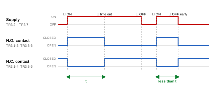
Figure 4.16-3. TR3 Interval-On timing diagram
- ① Supply ON: both contact sets switch immediately. The N.O. contacts (1-3, 8-6) close, and the N.C. contacts (1-4, 8-5) open. Timing starts.
- ② Time out: after the preset time t, the contacts return to their normal state, while the supply remains on.
- ③ Supply OFF: nothing changes at the contacts; the timer resets and is ready for the next cycle.
- ④–⑤ Supply removed early: if the supply is turned off before t is reached, the contacts return to normal immediately. The interval is cut short.
To run another interval, the supply must be turned off and back on. Leaving the supply on does not repeat the interval.
Pin Diagram
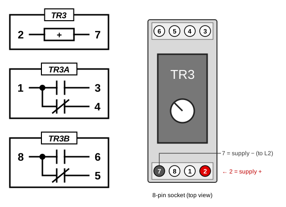
Figure 4.16-4. TR3 pin diagram and 8-pin socket terminal layout. In the drawing, terminal 2 (+) is shown in red and terminal 7 (−) in dark grey; the real socket has no color marks.
Contact Table
| Function | Pins | a (Common) | b (N.O.) | c (N.C.) | Written As |
|---|---|---|---|---|---|
| Supply | 2 – 7 | Pin 2 = + (orange wire), pin 7 = − (black wire to L2) | TR3:2, TR3:7 | ||
| Contact set TR3A | 1, 3, 4 | 1 | 3 | 4 | TR3:1-3, TR3:1-4 |
| Contact set TR3B | 8, 6, 5 | 8 | 6 | 5 | TR3:8-6, TR3:8-5 |
TR3 uses the same pin numbers as CR1 and TR1. In a ladder diagram, its contacts are drawn as ordinary N.O. and N.C. contacts labeled TR3, and the timing diagram explains the interval behavior (Section 4.13).
Application Example: Timed Tank Filling
- The operator presses START. A control relay seals in and energizes TR3.
- TR3's N.O. contact opens the fill valve (a lamp on your panel) immediately.
- After the preset time (for example, 30 seconds = 0.5 min), TR3's contact opens, and the valve closes automatically, even though the control relay remains energized.
- Pressing STOP drops out the control relay and removes TR3's supply, which ends the fill early if needed and resets TR3 for the next batch.
Checking TR3
With the power supply unplugged, set the knob to about 0.1 min (6 s) and wire:
- L1 → TR3:2 (orange) and TR3:7 → L2 (black): supply
- L1 → TR3:1 and TR3:3 → G1:1: G1 shows the N.O. contact
After instructor approval, plug in the power supply and start a stopwatch. G1 should turn on immediately and turn off automatically after about 6 seconds, while the supply stays on. Unplug and plug in again to repeat the interval.
Precautions and Common Mistakes
- Reading the scale in seconds. TR3's scale is in minutes. Setting "1" gives 60 seconds, not 1 second.
- Expecting the output to repeat. The interval runs once per power-up. The supply must be removed and reapplied for another interval.
- Confusing TR3 with TR1. TR1 delays the ON; TR3 delays the OFF while powered. Check the timing diagram before you choose.
- A flickering supply. Any interruption of the supply resets TR3 and restarts the interval on the next power-up.
- Trusting the dial. Measure the actual interval with a stopwatch.
4.17 TR4: Multi-Function (Dayton 5DRA3A)
Photo
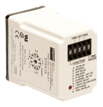 Figure 4.17-1. TR4: Dayton 5DRA3A |
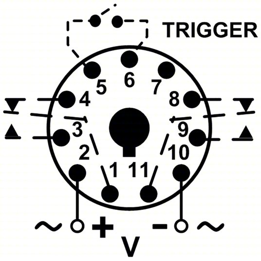 Figure 4.17-2. Wiring diagram (bottom view of the pins); the trigger is dashed because only some functions use it |
What It Is
TR4 is a multi-function, multi-range digital timer. One unit can be set to any of 10 timing functions and any delay from 0.05 seconds to 999 hours. Multi-function timers are popular in industry because one spare timer on the shelf can replace many single-function timers.
In the labs, you will use TR4 in three functions: A – On Delay, B – Interval On, and C – Off Delay. The other seven functions are described here so that you recognize them in the field.
Specifications
| Model | Dayton 5DRA3A (Macromatic TD-7 series design) |
| Functions | 10, selected with the FUNCTION thumbwheel (A – K) |
| Supply voltage | 24 V AC/DC, +10% / −15%; approx. 3 VA |
| Trigger | Dry contact across terminals 5 and 6 (functions C, D, G, H, J, K) |
| Time range | 0.05 s – 999 h, in 7 time units |
| Setting accuracy | ±0.1% of set time or ±50 ms, whichever is greater |
| Repeat accuracy | ±0.1% of set time or ±0.02 s, whichever is greater |
| Reset time | 0.1 s (0.04 s for triggered functions) |
| Minimum trigger pulse | 0.1 s |
| Indicator | LED: shows timing and timed-out conditions (steady or flashing, depending on the function) |
| Contacts | DPDT, 10 A at 240 V AC / 30 V DC |
| Life | Electrical 100,000 operations; mechanical 10,000,000 operations |
| Base | 11-pin octal (Section 4.10) |
Setting TR4
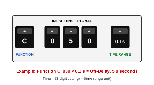
Figure 4.17-3. TR4 push-button thumbwheels
TR4 has five push-button thumbwheels. Each press of a thumbwheel's button advances it to the next value.
| Thumbwheel | Position | Sets |
|---|---|---|
| FUNCTION | Left | The timing function, A – K (Table below) |
| TIME SETTING | Middle three | A 3-digit number from 001 to 999 |
| TIME RANGE | Right | The time unit. The wheel positions are: S, 0.1s, .01s, S, 0.1s, .01s, H, 0.1h, M, 0.1m (some units appear twice) |
Delay time = (3-digit TIME SETTING) × (TIME RANGE unit)
| TIME RANGE | Unit | Range with 001 – 999 |
|---|---|---|
| .01s | 0.01 second | 0.01 – 9.99 s (use 005 or more: 50 ms minimum) |
| 0.1s | 0.1 second | 0.1 – 99.9 s |
| S | 1 second | 1 – 999 s |
| 0.1m | 0.1 minute | 0.1 – 99.9 min |
| M | 1 minute | 1 – 999 min |
| 0.1h | 0.1 hour | 0.1 – 99.9 h |
| H | 1 hour | 1 – 999 h |
| Desired Setting | FUNCTION | TIME SETTING | TIME RANGE |
|---|---|---|---|
| On Delay, 5.0 s | A | 050 | 0.1s |
| Interval On, 30 s | B | 030 | S |
| Off Delay, 2.5 s | C | 025 | 0.1s |
| On Delay, 1.5 min | A | 015 | 0.1m |
Set TR4 with the power OFF. The function cannot be changed while the supply is on. Unplug the power supply, set the FUNCTION, TIME SETTING, and TIME RANGE, then power up. Always read all five windows back before you start the lab.
The 10 Functions
| Code | Function | Started By | Operation | Used in Labs |
|---|---|---|---|---|
| A | On Delay | Supply | Supply ON starts timing; output switches at time-out. Supply OFF resets. | Yes |
| B | Interval On | Supply | Supply ON switches the output immediately; output returns at time-out. Supply OFF resets. | Yes |
| C | Off Delay | Trigger | Trigger closed: output switches immediately. Trigger opened: timing starts; output returns at time-out. Re-closing during timing restarts the delay. | Yes |
| D | One Shot | Trigger | Trigger closing switches the output for one time t. Further triggers during timing are ignored. | No |
| E | Flasher (OFF 1st) | Supply | Supply ON: output OFF for t, ON for t, repeating until the supply is removed. | No |
| F | Flasher (ON 1st) | Supply | Supply ON: output ON for t, OFF for t, repeating until the supply is removed. | No |
| G | On/Off Delay | Trigger | Trigger closing: output switches after t. Trigger opening: output returns after t. | No |
| H | 1 Shot Falling Edge | Trigger | Trigger opening switches the output for one time t. | No |
| J | Watchdog | Trigger | Each trigger closing switches the output and restarts timing. If no new trigger arrives within t, the output returns. | No |
| K | Triggered On Delay | Trigger | Trigger closing starts timing; output switches at time-out and stays until the trigger opens. Opening the trigger during timing resets it. | No |
For the triggered functions (C, D, G, H, J, K), the supply (2 and 10) must be ON all the time, and the trigger contact is wired directly across 5 and 6, exactly as for TR2 (Section 4.15).
Functions Used in the Labs
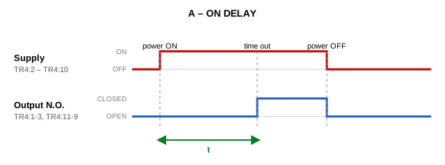
Figure 4.17-4. Function A – On Delay (works like TR1, Section 4.14)
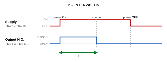
Figure 4.17-5. Function B – Interval On (works like TR3, Section 4.16)
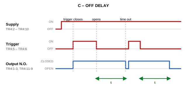
Figure 4.17-6. Function C – Off Delay (works like TR2, Section 4.15)
Because TR4 can do what TR1, TR2, and TR3 do, it is often used in the labs as a second On-Delay, Off-Delay, or Interval timer when a circuit needs two timers of the same kind.
Other Functions (for Reference)
In these diagrams, the supply is ON the whole time for the triggered functions.
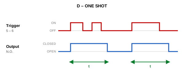
Figure 4.17-7. D – One Shot: extra triggers during timing are ignored.
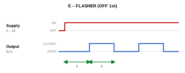
Figure 4.17-8. E – Flasher (OFF 1st). Example: a warning beacon that flashes while a fault exists.
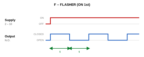
Figure 4.17-9. F – Flasher (ON 1st): the same as E, but the output starts ON.
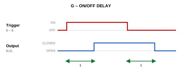
Figure 4.17-10. G – On/Off Delay: delayed both when the trigger closes and when it opens.
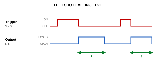
Figure 4.17-11. H – 1 Shot Falling Edge: the pulse starts when the trigger opens.
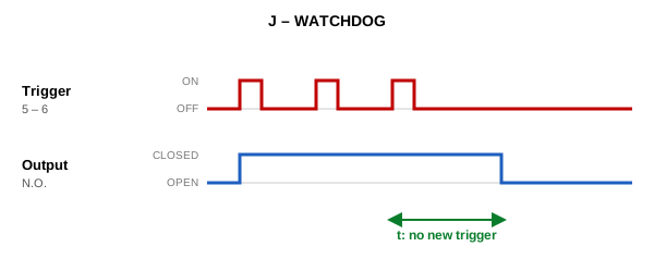
Figure 4.17-12. J – Watchdog: the output stays on while triggers keep arriving; it drops out when they stop for longer than t. Example: detecting that a conveyor sensor has stopped pulsing.
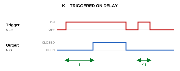
Figure 4.17-13. K – Triggered On Delay: like On Delay, but started by the trigger instead of the supply.
Pin Diagram
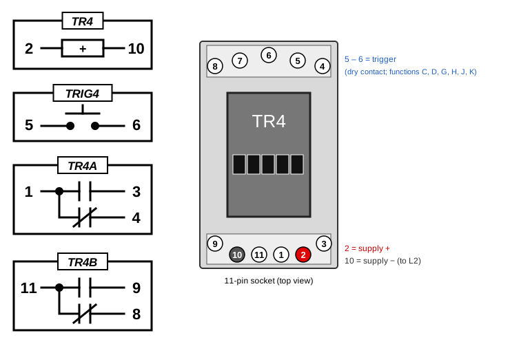
Figure 4.17-14. TR4 pin diagram and 11-pin socket terminal layout. In the drawing, terminal 2 (+) is shown in red and terminal 10 (−) in dark grey; the real socket has no color marks.
Contact Table
| Function | Pins | a (Common) | b (N.O.) | c (N.C.) | Written As |
|---|---|---|---|---|---|
| Supply | 2 – 10 | Pin 2 = + (orange wire), pin 10 = − (black wire to L2) | TR4:2, TR4:10 | ||
| Trigger | 5 – 6 | Dry contact only; used in functions C, D, G, H, J, K | TR4:5, TR4:6 | ||
| Contact set TR4A | 1, 3, 4 | 1 | 3 | 4 | TR4:1-3, TR4:1-4 |
| Contact set TR4B | 11, 9, 8 | 11 | 9 | 8 | TR4:11-9, TR4:11-8 |
TR4 has the same pin layout as TR2. Pin 7 is not used.
Checking TR4
With the power supply unplugged, set TR4 to A, 050, 0.1s (On Delay, 5.0 s) and wire:
- L1 → TR4:2 (orange) and TR4:10 → L2 (black): supply
- L1 → TR4:1 and TR4:3 → G1:1: G1 shows the N.O. contact
After instructor approval, plug in the power supply and start a stopwatch: G1 should turn on after 5.0 seconds. Then unplug, change the function to B, and repeat: G1 should turn on immediately and turn off after 5.0 seconds. Compare how close TR4's digital setting is to the measured time with the knob timers.
Precautions and Common Mistakes
- Voltage on 5 or 6. The trigger accepts only a dry contact. The manufacturer warns that applying voltage to these pins could damage the unit.
- Changing settings with power on. Set the function and time with the power supply unplugged.
- Wrong time unit. 050 means 5 seconds at 0.1s, 50 seconds at S, and 50 minutes at M. Always check the TIME RANGE window.
- Wrong function letter. A (On Delay) and K (Triggered On Delay) look similar on paper, but are started differently. B and D also differ: B is started by the supply, D by the trigger.
- Triggered the function with the supply switched. For C, D, G, H, J, and K, the supply must stay ON; only the trigger across 5-6 is switched.
- Very short settings. Use at least 50 ms. Settings below this are not reliable.
5. Building Your Control Panel
5. Building Your Control Panel
In this section you mount every component from Section 4 on a plywood board and complete the fixed wiring: the power, return, lamp, and input-device wires that stay in place for the whole semester. When you finish, every lab only needs short wires between terminals in the open center of the board.
Work through Steps 1 – 13 (Sections 5.1 – 5.13) in order, one tab at a time. Each step depends on the one before it. Do not plug in the power supply until Step 12 (Section 5.12) tells you to.
1.Layout
5.1 Panel Layout
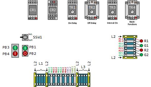
Figure 5.1-1. Control panel layout
The board is divided into four zones around an open center. Each zone has one job:
| Zone | Location | Components |
|---|---|---|
| Control | Top, 12 in rail | Socket bases, left to right: CR1, CR2, TR1, TR2, TR3, TR4 |
| Loads | Right, 4 in rail (vertical) | Lamp terminal strip and lamps R1, G1, R2, G2 |
| Inputs and power | Bottom, 8 in rail | Main terminal strip (L1, PB1 – PB4, SWL, SWR, L3, L2) and the 24 V DC jack adapter |
| Input devices | Left | PB1/PB2 twin button, PB3/PB4 station box, SSW1 selector switch |
| Open wiring area | Center | Nothing. This space is reserved for the wires you add in each lab. |
Rule of the layout: fixed wiring outside, lab wiring inside
| Fixed Wiring | Lab Wiring | |
|---|---|---|
| What | Power, L2 returns, lamps, input devices (Sections 5.9 – 5.10) | The circuit of each lab |
| Where it runs | Along the outside edges of the board, around the zones | Across the open center of the board |
| Terminal clamps | The outer clamp, facing the edge of the board: the lower clamps of the main strip and the right clamps of the lamp strip | The inner clamp, facing the center: the upper clamps of the main strip and the left clamps of the lamp strip |
| When removed | Never. Installed once and left in place for the whole semester. | After every lab. All lab wires are removed before you put the panel away. |
Keeping the two kinds of wiring apart means you never disturb the fixed wiring while you build or remove a lab circuit, and every lab starts from the same clean panel.
2.Parts and Tools
5.2 Parts and Tools
| Item | Qty | Section |
|---|---|---|
| Plywood board, 20 in × 12 in × 1/2 in (metric: 500 × 300 mm) | 1 | — |
| Slotted aluminum DIN rail: 12 in, 8 in, 4 in (metric: 300, 200, 100 mm) | 1 each | 4.2 |
| Pan-head wood screws for the rails, #6 × 3/8 in | 7 | 5.4 |
| Socket bases: 8-pin (3), 11-pin (2), 14-pin (1) | 6 | 4.10 |
| Relays CR1 (Omron MKS2PIN) and CR2 (RONE HH54PL) | 1 each | 4.11, 4.12 |
| Linergy TR terminals: blue and grey, with DSS2.5N-02P jumpers | per Section 4.3 | 4.3, 4.4 |
| CGT10U green-yellow ground terminals | 6 | 4.5 |
| Pilot lamps R1, R2 (red) and G1, G2 (green) | 4 | 4.9 |
| PB1/PB2 twin button, PB3/PB4 station box, SSW1 selector switch | 1 each | 4.6 – 4.8 |
| 24 V DC 2 A adapter with DC-jack-to-screw-terminal adapter | 1 | 4.1 |
| 18 AWG solid wire: red, black, green, yellow | as needed | — |
| Thick double-sided foam mounting tape | 1 roll (shared) | 5.11 |
| Klein 32581 (1/8 in slotted bit), Klein 7314 (#1 combo tip), wire stripper, multimeter | — | 2.7 |
| Tape measure or ruler, carpenter's square, pencil, awl or small nail | — | — |
Timers TR1 – TR4 are not in your kit. There are only a few of each, so your instructor hands them out for the labs that need them, and they are shared between students. You install their socket bases now; the timers themselves are plugged in only during those labs.
3.Mark the Board
5.3 Mark the Layout on the Plywood
Imperial Dimensions (inch)
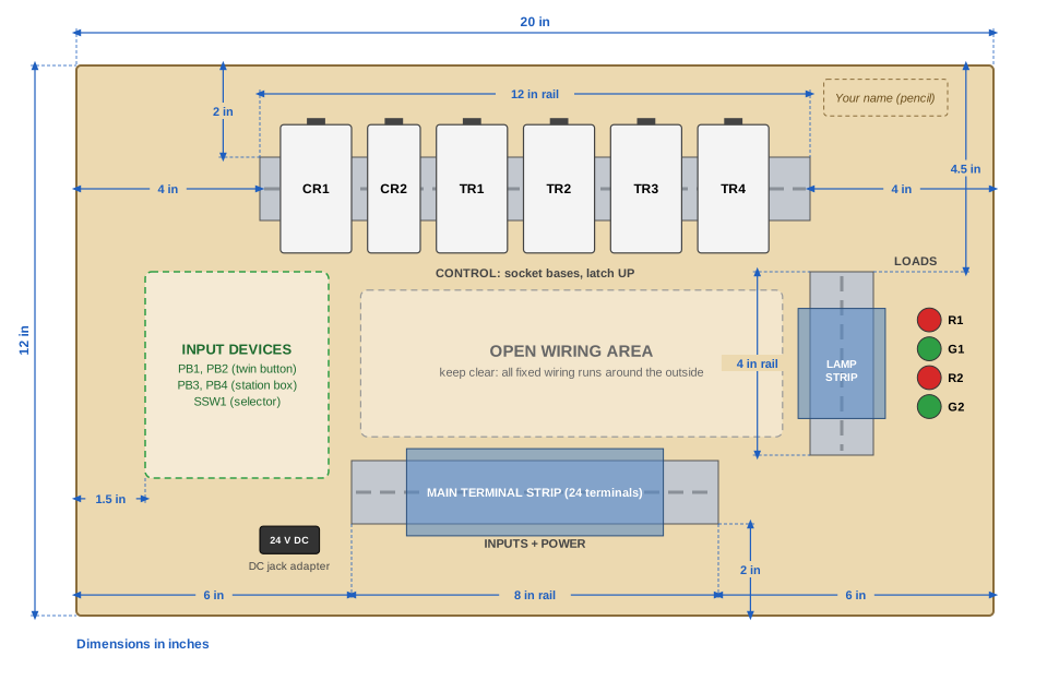
Figure 5.3-1. Rail positions and edge margins (inches)
Metric Dimensions (mm)
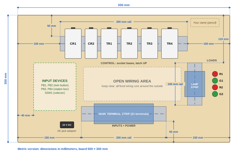
Figure 5.3-2. Metric version: 500 × 300 mm board with 300, 200, and 100 mm rails
The metric version uses round numbers and is not an exact conversion of the inch version. Pick one system for your board and use only that system; the values in parentheses in the table below are for the metric board.
Lay the board flat with the long side horizontal. Using a tape measure and a carpenter's square, draw light pencil lines for the rail positions:
| Rail | Horizontal Position | Vertical Position |
|---|---|---|
| Top, 12 in / 300 mm (horizontal) | Centered: 4 in (100 mm) from each side | Top edge of the rail 2 in (50 mm) below the top edge of the board |
| Bottom, 8 in / 200 mm (horizontal) | Centered: 6 in (150 mm) from each side | Bottom edge of the rail 2 in (50 mm) above the bottom edge of the board |
| Right, 4 in / 100 mm (vertical) | Left edge of the rail 4 in (100 mm) from the right edge of the board (lined up with the right end of the top rail) | Top end of the rail 4.5 in (110 mm) below the top edge |
| Input devices | At least 1.5 in (40 mm) from the left edge | Between the top and bottom rails |
Why the margins matter:
- Room for wires and tools. Wires leave the socket bases and terminal blocks from both sides. The 2 in margins above the top rail and below the bottom rail give you room to route wires and to turn a screwdriver.
- A place for the fixed wiring. The power, return, and input wires run in the margins along the edges, not across the center.
- Protection. Nothing overhangs the edge of the board, so components are not knocked when the board is carried or stacked, and you can hold the board by its edges without touching any terminal.
4.Mount the Rails
5.4 Mount the DIN Rails
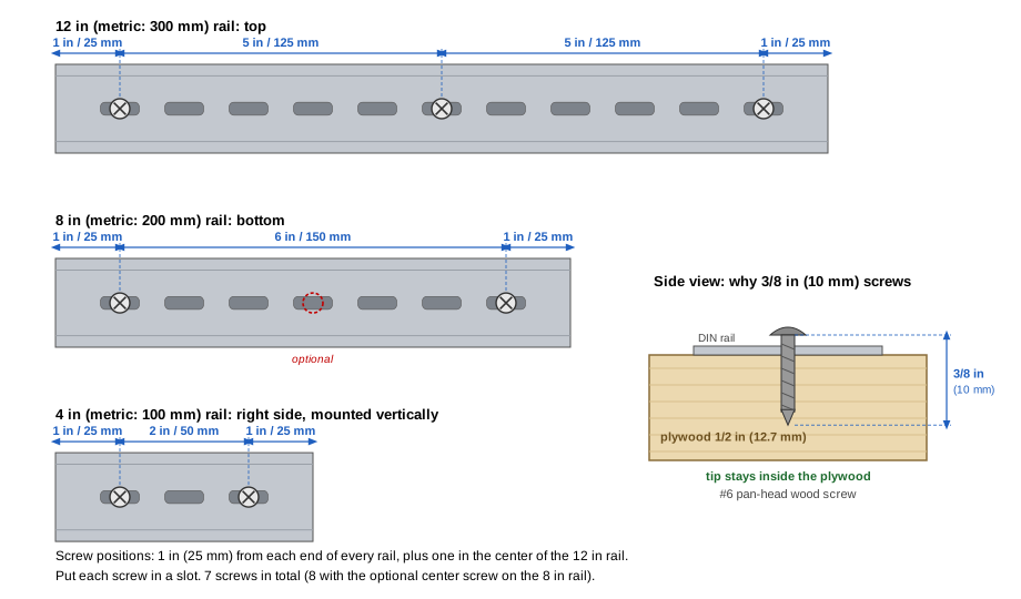
Figure 5.4-1. Screw positions on each rail, and why the screws are 3/8 in (10 mm) long
- Place each rail on its pencil marks, with the slots along the center line of the rail.
- Mark the screw positions through the slots: about 1 in (25 mm) from each end of every rail, plus one in the center of the 12 in rail. That is 3 + 2 + 2 = 7 screws. You may add an optional center screw on the 8 in rail (Figure 5.4-1).
- Make a small starter hole at each mark with an awl or a nail, so the screw goes in straight.
- Fasten the rails with #6 × 3/8 in (10 mm) pan-head wood screws. A longer screw can come out the back of the 1/2 in plywood.
- Tighten until the rail is held flat and does not move. Stop there; over-tightening strips the wood.
- Check that the top and bottom rails are level and the right rail is vertical. Adjust now, before anything is mounted on them.
5.Sockets and Relays
5.5 Install the Socket Bases and Relays
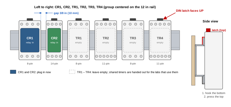
Figure 5.5-1. Socket bases on the top rail: latch up, CR1 and CR2 plugged in, timer sockets empty
- Arrange the six socket bases on the top rail in this order, left to right: CR1 (8-pin), CR2 (14-pin), TR1 (8-pin), TR2 (11-pin), TR3 (8-pin), TR4 (11-pin). The sockets are not labeled, so this position order is how everyone identifies them (Section 4.10).
- Mount every socket base with its DIN latch facing UP. Hook the bottom of the socket onto the lower lip of the rail first, then press the top until the latch clicks (Section 4.2).
- Leave a gap of about 3/8 in (10 mm) between neighboring sockets, and center the group on the rail. The gaps give your fingers, the screwdriver, and wires room between the sockets.
- Plug CR1 into the first socket and CR2 into the second. Line up the key or the pins, and push straight in until the relay is fully seated. Do not rock it from side to side; the pins bend.
- Leave the four timer sockets empty. Timers are plugged in only during the labs that use them (Section 5.2).
Shared timers: when a timer is handed out, treat it as borrowed equipment. Plug it in and pull it out straight, never force it, and return it with the knob or thumbwheels where you found them.
6.Terminal Strips
5.6 Assemble the Terminal Strips
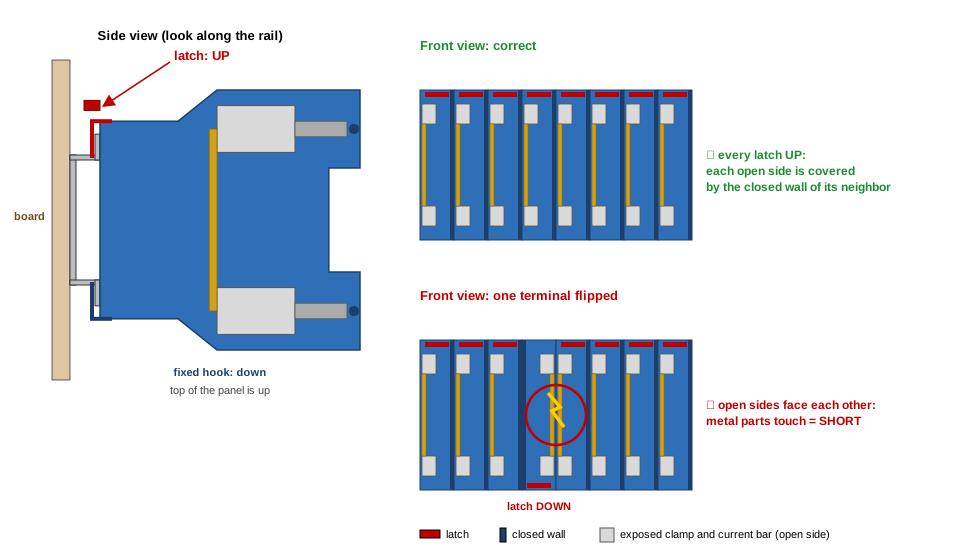
Figure 5.6-1. Mount every terminal with its latch UP. A flipped terminal puts two open sides face to face and shorts them together.
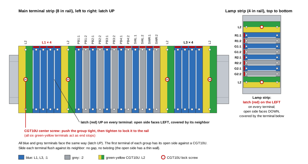
Figure 5.6-2. Terminal strips on the rails: order, latch and open-side direction, and CGT10U lock screws
- Bottom rail (main strip), left to right: L2 | L1 × 4 | L2 | PB1:1 PB1:2 PB2:1 PB2:2 PB3:1 PB3:2 PB4:1 PB4:2 SWL:1 SWL:2 SWR:1 SWR:2 | L2 | L3 × 4 | L2
- Right rail (lamp strip), top to bottom: L2, R1:1, R1:2, G1:1, G1:2, R2:1, R2:2, G2:1, G2:2, L2
Blue terminals are L1, L3, and every :1 terminal; grey terminals are every :2 terminal; green-yellow CGT10U terminals are L2.
- Latch direction. Each Linergy TR terminal has a spring latch on one end of its foot and a fixed hook on the other. On each strip, mount every terminal with its latch pointing the same way (Figures 5.6-1 and 5.6-2):
Strip Latch How to Mount Open Side Faces Main strip (bottom, horizontal rail) UP Hook the bottom on the rail first, then press the top until the latch clicks. Left Lamp strip (right, vertical rail) LEFT Hook the right side on the rail first, then press the left side until the latch clicks. Down - Why it matters. Each terminal is closed on one side and open on the other, where its clamps and current bar are exposed. When every latch points the same way, each open side is covered by the closed wall of its neighbor. If one terminal is flipped, its open side faces the open side of the next terminal, and their metal parts can touch: two different terminals are then shorted together. Before you go on, check that every latch on the strip points the same way.
- Snap the terminals on one at a time and slide each one against the one before it until they sit flush, with no gap. Push gently and straight. The open side has a thin wall that cracks if the terminal is twisted or forced.
- Lock the strip with the CGT10U terminals. A CGT10U has a screw in its center that clamps it to the rail. Push the whole group tight, then tighten the center screw of each CGT10U with the Klein 32581. The CGT10U terminals act as end stops and hold all the terminals between them in place.
- Check that the strip does not slide on the rail and that each terminal is in the right position.
7.Jumpers
5.7 Install the Jumpers (L1 and L3)
The four blue L1 terminals must be joined into one bus, and so must the four blue L3 terminals. Three DSS2.5N-02P jumpers do this for each group (Section 4.4).
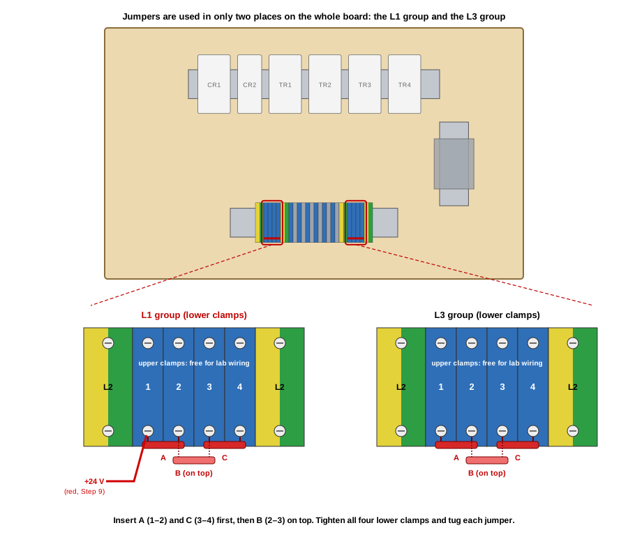
Figure 5.7-1. Jumper locations on the board, and jumpers A, B, and C in the lower clamps of the L1 and L3 groups
- Open the clamps. With the Klein 32581, fully open the lower clamps of the four L1 terminals. Look into each clamp to confirm it is completely open.
- Insert A and C. Slide jumper A into the lower clamps of terminals 1 – 2, and jumper C into the lower clamps of terminals 3 – 4, until each red handle touches the terminal bodies.
- Insert B on top. Slide jumper B into the lower clamps of terminals 2 – 3, on top of the legs of A and C.
- Tighten all four lower clamps until firm. Do not over-tighten. The clamps of terminals 2 and 3 each hold two jumper legs.
- Tug each jumper. None of them may move.
- Repeat steps 1 – 5 for the four L3 terminals.
- Check with the multimeter (continuity mode): all four L1 terminals beep to each other, all four L3 terminals beep to each other, and L1 does not beep to L3 or to any L2 terminal.
Never place a jumper on an L2, input, or lamp terminal. The CGT10U terminals at the ends of each group are not jumpered; they keep L1 and L3 apart from L2 and from each other. All four upper clamps stay free for lab wiring.
8.Wiring Rules
5.8 Wiring Rules for the Panel
These rules apply to every wire you install, now and in every lab.
| Wire Color | Use |
|---|---|
| Red | +24 V from the adapter to L1 |
| Black | GND: the adapter − to L2, every coil or timer supply −, every lamp −, and the bonding wire between L2 terminals |
| Orange | The coil + terminal of a relay or timer (added in each lab) |
| Green pairs | PB1, PB3, SWL (Section 5.10) |
| Yellow pairs | PB2, PB4, SWR (Section 5.10) |
Stripping
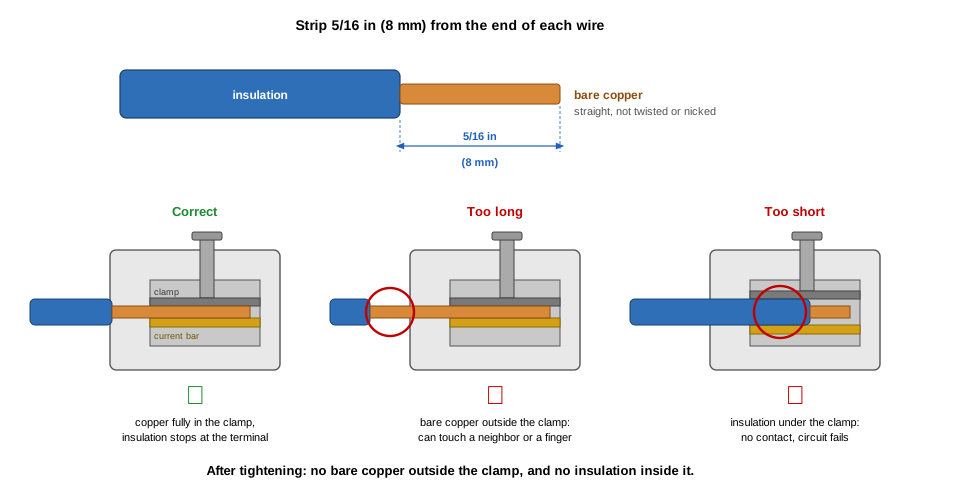
Figure 5.8-1. Strip length: no bare copper outside the clamp, and no insulation inside it
- Strip 5/16 in (8 mm) from the end of each wire. That is the depth of the terminal clamp.
- Too long: bare copper sticks out of the clamp, where it can touch a neighboring terminal or a finger.
- Too short: the clamp grips the insulation instead of the copper, and the connection fails.
- After tightening, you should see no bare copper outside the clamp and no insulation inside it.
Making the Connection
- Open the clamp fully. Turn the screw counterclockwise, then look into the terminal to confirm the clamp is completely open. A partly open clamp lets the wire slip in beside the clamp instead of into it; it feels tight but makes no contact.
- Insert the stripped end straight in, all the way to the insulation.
- Tighten until the screw is firm, then stop. Never tighten as hard as you can: the small screws strip their threads easily, and a stripped terminal must be replaced.
- Tug test: pull the wire gently. If it moves, open the clamp and redo it.
More than one wire in a clamp: twist the stripped ends together and insert them together. After tightening, tug each wire separately and check each one with the multimeter (one probe on the terminal screw, the other on the far end of the wire) to make sure every wire is really clamped (Section 4.3).
Routing
- Cut every wire to a suitable length: long enough to follow the edge of the board with gentle bends, but with no loops or extra slack.
- Run wires along the edges and around the zones, never across the open wiring area. Bend corners neatly at right angles.
- Keep wires flat on the board, away from screw heads, relay latches, and the top of the timer sockets.
9.Fixed Wiring
5.9 Fixed Power, Return, and Lamp Wiring
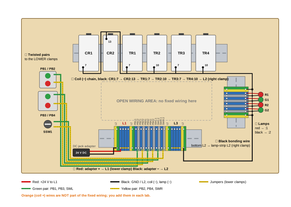
Figure 5.9-1. Fixed wiring. The numbers match the steps below and in Section 5.10.
① Power Supply
- Fix the DC-jack-to-screw-terminal adapter to the board with foam tape, to the left of the main terminal strip in the bottom margin.
- Red: adapter + to the lower clamp of the first (leftmost) L1 terminal. Loosen that clamp, insert the red wire beside the leg of jumper A, and retighten. Tug-test both the wire and the jumper. The +24 V wire is the only wire allowed to share a jumper clamp (Section 4.4).
- Black: adapter − to the lower clamp of the left-end L2 (CGT10U).
② Bonding Wire
Run a black wire from the lower clamp of the right-end L2 on the bottom strip, along the bottom margin and up the right side of the lamp strip, to the right clamp of the bottom L2 on the lamp strip. This joins the two strips' L2 terminals (Section 4.5).
③ Coil and Supply Returns
Every relay coil and timer supply has its − terminal on L2, so these are wired now, once, with one black wire chained from socket to socket:
| Socket | CR1 | CR2 | TR1 | TR2 | TR3 | TR4 |
|---|---|---|---|---|---|---|
| (− GND) terminal | 7 | 13 | 7 | 10 | 7 | 10 |
- Start at CR1:7 and chain CR1:7 → CR2:13 → TR1:7 → TR2:10 → TR3:7 → TR4:10.
- Run the chain close along the bottom of the socket row. CR2:13 is on the top row of its socket, so pass up and back down through the gaps on either side of CR2.
- At each socket terminal, place the incoming and outgoing wires under the same pressure plate, one on each side of the screw, and tighten with the Klein 7314.
- From TR4:10, continue past the top of the lamp strip and down its right side to the right clamp of the top L2 on the lamp strip.
In the labs, you then add only the orange wire to each coil + terminal (CR1:2, CR2:14, TR1:2, TR2:2, TR3:2, TR4:2).
④ Lamps
- Mount the four lamps to the right of the lamp strip, top to bottom: R1, G1, R2, G2, each one level with its own terminals.
- Connect each lamp's red lead to the right clamp of its :1 terminal, and its black lead to the right clamp of its :2 terminal. The lamp leads are 6 in long, so keep the lamps close to the strip.
- Join the right clamps of R1:2, G1:2, R2:2, and G2:2 to L2 with black wire, along the right side of the strip (Section 4.9).
Lamp strip rule: every fixed wire on the lamp strip (lamp leads, the L2 return wires, the bonding wire, and the coil return chain) is on the right side. The left clamps are the inner side and are kept free for lab wiring. In the labs you use only the left clamp of each :1 terminal: bring +24 V there, and the lamp lights.
The right clamps of the two L2 terminals each hold two fixed wires: the lamp return wire plus the coil return chain (top L2), or plus the bonding wire (bottom L2). The CGT10U clamp is large enough for two wires: twist the two stripped ends together before inserting them, then tug each wire separately and check each one with the multimeter (Section 4.3).
10.Wire the Inputs
5.10 Wire the Input Devices
Wire each input device while it is still loose, before it is fixed to the board. Each contact uses two wires of the same color, twisted together:
| Device | Contact | Wire Pair | Terminals |
|---|---|---|---|
| PB1 (twin button, green "I") | N.O. | 2 × green | PB1:1, PB1:2 |
| PB2 (twin button, red "O") | N.C. | 2 × yellow | PB2:1, PB2:2 |
| PB3 (station box, START) | N.O. | 2 × green | PB3:1, PB3:2 |
| PB4 (station box, STOP) | N.C. | 2 × yellow | PB4:1, PB4:2 |
| SSW1, SWL contact block | N.O. | 2 × green | SWL:1, SWL:2 |
| SSW1, SWR contact block | N.O. | 2 × yellow | SWR:1, SWR:2 |
The two colors alternate along the terminal strip (green, yellow, green, yellow ...), so you can see at a glance which pair belongs to which terminal.
- Connect the device end. Attach the two wires to the two screw terminals of the contact block (Sections 4.6 – 4.8). On the twin button, leave the middle lamp terminals empty: that lamp is 220 V. On the station box, pass the wires through the cable gland first, then tighten the gland.
- Twist the pair. Twist the two wires together evenly, about 2 – 3 turns per inch. A twisted pair stays together, looks neat, and is easy to trace.
- Plan the route. Hold the device in its final position (Figure 5.3-1) and lay the pair along the left margin and then the bottom margin to its two terminals.
- Cut to length. Leave about 1 in of extra length at the device end so it can be removed for service. Untwist about 1 in at the terminal end so each wire reaches its own terminal.
- Connect to the LOWER clamps. Strip 5/16 in and connect the pair to the lower clamps of its :1 and :2 terminals. The upper clamps stay free for lab wiring.
- Check with the multimeter (continuity mode) that each pair reaches the correct two terminals before you go on to the next device.
11.Mount the Inputs
5.11 Mount the Input Devices
- When all six pairs are connected and checked, place the devices in the input zone: SSW1, the PB1/PB2 twin button, and the PB3/PB4 station box (Figure 5.1-1), at least 1.5 in from the left edge.
- Arrange the wire pairs so they leave each device in the same direction and run together, side by side, along the left and bottom margins. No pair crosses another, and none crosses the open wiring area.
- Clean the bottom of each device, apply thick double-sided foam tape, and press the device firmly onto the board for about 30 seconds.
- Stand back and look at your board. Wires should run straight, turn at neat corners, and lie flat. A professional-looking panel is easier to troubleshoot and safer to use.
12.Inspect and Test
5.12 Inspect and Test
Keep the adapter unplugged from the wall and its DC plug disconnected from the jack while you make these tests. Use the multimeter in continuity (Ω, beep) mode unless the table says otherwise.
Visual Inspection
- No bare copper outside any clamp, and no loose wire when tugged.
- No stripped or cross-threaded screws.
- Terminal strips tight on the rails; CGT10U center screws tight.
- Socket bases latched, CR1 and CR2 fully seated, timer sockets empty.
- Nothing connected to the twin button's lamp terminals.
Multimeter Tests
| Test Between | Condition | Expected Result |
|---|---|---|
| All four L1 terminals | — | Beep (jumpers connected) |
| All four L3 terminals | — | Beep |
| All six L2 terminals (both strips) | — | Beep (rails and bonding wire connected) |
| L1 – L2 | — | No beep (OL). A beep here is a short circuit; find it before going on. |
| L1 – L3, and L3 – L2 | — | No beep |
| PB1:1 – PB1:2, PB3:1 – PB3:2 | Released / pressed | No beep / beep (N.O.) |
| PB2:1 – PB2:2, PB4:1 – PB4:2 | Released / pressed | Beep / no beep (N.C.) |
| SWL:1 – SWL:2 | Center / held LEFT | No beep / beep |
| SWR:1 – SWR:2 | Center / held RIGHT | No beep / beep |
| Any input terminal – L1, and – L2 | Any position | No beep |
| CR1:2 (red probe) – L2 (black probe) | Ω mode | About 48 Ω (CR1 coil through the black chain) |
| CR2:14 (red probe) – L2 (black probe) | Ω mode | About 650 Ω (CR2 coil) |
| TR1:7, TR2:10, TR3:7, TR4:10 – L2 | — | Beep (return chain complete) |
| Each lamp :1 – L2 | Ω mode | Not 0 Ω. The lamp is a load; 0 Ω means a short. |
Power-On Test (after your instructor approves the wiring)
- Connect the DC plug and plug the adapter into the wall. The adapter LED turns on.
- Measure L1 – L2 in DC volts: about 24 V.
- Measure L3 – L2: 0 V. L3 is powered only after the MCR circuit is built in the labs.
- Unplug the adapter. The panel is ready.
13.Sign and Clean Up
5.13 Sign Your Panel
Write your name in pencil in the top-right corner of the board (Figure 5.3-1). Pencil can be erased when the board is passed on to the next student. You will use this panel for every lab this semester.
After every lab: unplug the adapter, remove all lab wires from the center of the board and from the inner clamps, and return any timers you borrowed. Do not remove or loosen any fixed wiring. If a fixed wire comes loose, reconnect it and repeat the tests in Section 5.12 for that wire.
6. Lab Manual Structure
Lab Manual Structure: 5 Parts, 20 Labs
The labs are arranged from simple to complex. Each part adds one new idea: first basic relay logic, then two push-button stations and interlocks, then single timers, then timer combinations, and finally complete machines that use everything together. Every lab is based on a real industrial application.
Part A — Basic Relay Logic (one start/stop station, no timers)
| Lab | Title | Industrial application | Main devices |
|---|---|---|---|
| 01 | Jog (Inching) Control | Crane and winder jog positioning | PB1, CR1, G1 |
| 02 | Three-Wire Start/Stop Control with Seal-In | Conveyor motor start/stop | PB1, PB2, CR1, G1 |
| 03 | Machine Status Stack Light | Machine RUNNING/STOPPED tower light | PB1, PB2, CR1, G1, R1 |
Part B — Two Stations and Interlocks (no timers)
| Lab | Title | Industrial application | Main devices |
|---|---|---|---|
| 04 | Two-Location Control | Long conveyor with a station at each end | PB1–PB4, CR1, G1, R1 |
| 05 | Jog / Run Selection | Packaging machine, threading, and production | PB1–PB3, CR1, CR2, G1, R1 |
| 06 | Forward/Reverse Control with Electrical Interlock | Loading-dock roll-up door | PB1–PB3, CR1, CR2, G1, R1 |
| 07 | Conveyor Sequence Interlock | Recycling plant feed and discharge conveyors | PB1–PB4, CR1, CR2, G1, R1 |
Part C — Single Timers (one start/stop station)
| Lab | Title | Industrial application | Timer |
|---|---|---|---|
| 08 | Pre-Start Warning Delay | Conveyor start-up warning horn and beacon | TR1 on-delay |
| 09 | Hold-to-Start Safety | Industrial mixer deliberate-action start | TR1 on-delay |
| 10 | Post-Stop Cooling Fan | Curing oven fan cool-down | TR2 off-delay |
| 11 | Automatic Lubrication Shot | CNC machine lube pump | TR3 interval |
| 12 | Multi-Function Timer Modes | Universal spare timer for maintenance | TR4 (all three modes) |
Part D — Timer Combinations (one start/stop station)
| Lab | Title | Industrial application | Timers |
|---|---|---|---|
| 13 | Warning Beacon Flasher | Tank high-level alarm beacon | TR1 + TR4 |
| 14 | Pump Proof-of-Flow Fault Trip | Cooling-water pump trips if no flow is proven in time | TR1 |
| 15 | Star-Delta (Y-Δ) Starter | Reduced-voltage start of a 75 hp pump motor | TR1 + TR4 |
Part E — Two Stations with Timers (integrated applications)
| Lab | Title | Industrial application | Timers |
|---|---|---|---|
| 16 | Forward/Reverse with Anti-Plugging Delay | Heavy reversible shuttle conveyor: coast-down lockout | TR1 |
| 17 | Controlled Stop vs. Emergency Stop | CNC lathe: Stop Category 1 vs. Category 0 with a master control relay and switched bus L3 | TR2 |
| 18 | Two-Hand Anti-Tie-Down Control | Punch press: concurrency window, anti-tie-down, anti-repeat | TR3 + TR4 |
| 19 | Burner Pre-Purge and Ignition Permissive | Gas-fired boiler: purge, trial for ignition, flame supervision | TR1 + TR3 |
| 20 | Capstone: Complete Conveyor Station | Student-designed outbound conveyor: E-stop and L3, start-up warning, run-on, cleaning spray | TR1, TR2, TR3 (student choice) |
Format of Each Lab
- Labs 01–03 are fully worked examples: the ladder diagram and wiring table are provided, so you can learn how to read a diagram, identify the pins, wire it, and test it.
- From Lab 04 on, you design the circuit yourself, guided by a step-by-step drawing guide, the node method for building the wiring table, and a trace-with-pencil check. Your worksheet must be approved by the instructor before you start wiring.
- Every lab includes an application scenario, functional requirements, key wiring points, a meter check before power-up, a test and acceptance table, troubleshooting, review questions, and a section showing where the same circuit pattern is used in industry.
7. Quick-Reference Card
7. Quick-Reference Card
This card collects the facts you will look up most often while wiring a lab: buses, wire colors, terminal assignments, relay and timer pins, timer functions, and the checks before and after each lab. Print this section and keep it at your bench. The details behind each entry are in Section 4 (components) and Section 5 (panel).
7.1 Buses and Wire Colors
| Item | Meaning | Wire Color |
|---|---|---|
| L1 | +24 V DC, always on while the adapter is plugged in | Red |
| L2 | 0 V (GND, return), green-yellow CGT10U terminals | Black |
| L3 | Controlled bus, fed from L1 through an MCR N.O. contact | Any other color |
| Coil / supply + | Relay coil + or timer supply + | Orange |
| Coil / supply − | Relay coil − or timer supply − to L2: already wired (fixed wiring) | Black |
| Input device pairs | PB1, PB3, SWL / PB2, PB4, SWR to the terminal strip: already wired (fixed wiring) | Green / Yellow |
| All other lab wires | Contacts, push buttons, lamps | Any color except red, black, orange |
Wire: 18 AWG solid, strip 5/16 in (8 mm). Terminal blocks: Klein 32581 (1/8 in slotted). Socket bases: Klein 7314 (#1 combo tip).
7.2 Fixed Wiring and Lab Wiring
| Fixed Wiring | Lab Wiring | |
|---|---|---|
| What | Power, L2 returns, coil (−) chain, lamps, input devices | The circuit of the lab |
| Main strip (bottom) | Lower clamps (outer side) | Upper clamps (inner side) |
| Lamp strip (right) | Right clamps (outer side) | Left clamps (inner side) |
| Where it runs | Around the edges of the board | Across the open center |
| Removed | Never | After every lab |
7.3 Contact Naming
| a | Common |
| a – b | N.O. (normally open): closes when the relay energizes or the timer times out |
| a – c | N.C. (normally closed): opens when the relay energizes or the timer times out |
| Notation | Device:pin, for example CR1:1-3 (N.O.), TR2:5, G1:1 |
7.4 Main Terminal Strip (Bottom Rail, Left to Right)
| L2 | L1 × 4 | L2 | PB1:1 | PB1:2 | PB2:1 | PB2:2 | PB3:1 | PB3:2 | PB4:1 | PB4:2 | SWL:1 | SWL:2 | SWR:1 | SWR:2 | L2 | L3 × 4 | L2 | ||||||
Blue = L1, L3 (four terminals joined by jumpers) or an input's :1 terminal. Grey = an input's :2 terminal. Green-yellow = L2. Cell colors above follow the terminal colors. Connect lab wires to the upper clamps only.
7.5 Input Devices
| Name | Device | Contact | Terminals | Closed When |
|---|---|---|---|---|
| PB1 | Twin button, green "I" | N.O. | PB1:1, PB1:2 | Pressed |
| PB2 | Twin button, red "O" | N.C. | PB2:1, PB2:2 | Released |
| PB3 | Station box, START | N.O. | PB3:1, PB3:2 | Pressed |
| PB4 | Station box, STOP | N.C. | PB4:1, PB4:2 | Released |
| SWL | SSW1, left contact block | N.O. | SWL:1, SWL:2 | Lever held LEFT |
| SWR | SSW1, right contact block | N.O. | SWR:1, SWR:2 | Lever held RIGHT |
Never wire the middle lamp of the twin button. It is a 220 V lamp. SSW1 springs back to CENTER (OFF) when released.
7.6 Output Devices (Lamp Strip, Right Rail)
| Name | Color | You Wire | Already Wired (Right Clamps) |
|---|---|---|---|
| R1, R2 | Red | Left clamp of R1:1, R2:1 | Lamp leads; R1:2, R2:2 to L2 |
| G1, G2 | Green | Left clamp of G1:1, G2:1 | Lamp leads; G1:2, G2:2 to L2 |
To light a lamp, bring +24 V to the left clamp of its :1 terminal. The return is already connected.
7.7 Relays and Timers: Pin Summary
| Device | Base | Coil / Supply + (orange, you wire) / − (already wired) | Set A a-b / a-c | Set B a-b / a-c | Other |
|---|---|---|---|---|---|
| CR1 Omron MKS2PIN | 8-pin | 2 / 7 | 1-3 / 1-4 | 8-6 / 8-5 | AC24 coil on DC: about 0.5 A, gets warm |
| CR2 RONE HH54PL | 14-pin | 14 / 13 | 9-5 / 9-1 | 10-6 / 10-2 | Set C 11-7 / 11-3 Set D 12-8 / 12-4 3 A contacts |
| TR1 On-Delay | 8-pin | 2 / 7 | 1-3 / 1-4 | 8-6 / 8-5 | 0.6 – 60 s |
| TR2 Off-Delay | 11-pin | 2 / 10 | 1-3 / 1-4 | 11-9 / 11-8 | Trigger 5-6; 0.6 – 60 s |
| TR3 Interval-On | 8-pin | 2 / 7 | 1-3 / 1-4 | 8-6 / 8-5 | 0.03 – 3 min |
| TR4 Multi-Function | 11-pin | 2 / 10 | 1-3 / 1-4 | 11-9 / 11-8 | Trigger 5-6; function A, B, C |
Top rail order, left to right: CR1, CR2, TR1, TR2, TR3, TR4. The sockets are not labeled, so count positions. Timers are shared: your instructor hands them out for the labs that need them.
7.8 Socket Terminal Layouts (Top View)
Latch UP. Every socket base is mounted with its DIN latch at the top (Section 5.5), and the layouts below are drawn that way. A socket mounted upside down puts every pin number in the wrong place, so check the latch before you trust these drawings.
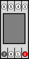 8-pin: CR1, TR1, TR3 |
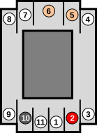 11-pin: TR2, TR4 |
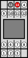 14-pin: CR2 |
| ● Red | Coil or supply + (orange wire): 2, 2, 14 |
| ● Dark grey | Coil or supply − (already wired to L2): 7, 10, 13 |
| ● Orange | Trigger 5 – 6 (TR2, TR4 only): dry contact only |
The colors are only in the drawings; the real sockets have no color marks. Always confirm against the numbers molded on the socket. Figures 4.11-2, 4.12-2, 4.14-4, 4.15-5, 4.16-4, and 4.17-14 show the full drawings.
7.9 Timer Functions at a Glance
| Function | Timer | Controlled By | Output | Ladder Contacts |
|---|---|---|---|---|
| On-Delay | TR1, TR4-A | Supply | Delay ON, instant OFF | N.O.T.C. / N.C.T.O. |
| Interval-On | TR3, TR4-B | Supply | Instant ON, timed OFF while powered | N.O. / N.C. + timing diagram |
| Off-Delay | TR2, TR4-C | Trigger 5-6 (supply always on) | Instant ON, delay OFF after the trigger opens | N.O.T.O. / N.C.T.C. |
TR4 setting: time = 3-digit TIME SETTING × TIME RANGE unit. Example: function A, 050, 0.1s = On-Delay, 5.0 s. Change the thumbwheels only with the power off.
7.10 Connecting a Wire
- Strip 5/16 in (8 mm): no bare copper outside the clamp, no insulation inside it.
- Open the clamp fully and look to confirm it is open before inserting the wire.
- Tighten until firm. Never tighten as hard as you can; the screw threads strip easily.
- Tug the wire. It must not move.
- Two wires in one clamp: twist the stripped ends together and insert them together. Tug each wire separately and check each one with the multimeter (one probe on the terminal screw, the other on the far end of the wire).
- No control wire in a clamp that holds a jumper leg (L1, L3 lower clamps).
7.11 Before You Plug In
- Lab wires are only in the upper clamps of the main strip and the left clamps of the lamp strip.
- Each relay coil and timer supply in the circuit has its orange + wire. The − side is already on L2.
- Nothing but a dry contact is connected to TR2:5, TR2:6, TR4:5, or TR4:6.
- No wire runs directly from L1 (or L3) to L2 without passing through a load.
- Every wire is stripped 5/16 in, fully inserted, tight, and tug-tested; no bare copper shows outside a clamp.
- Relays and timers are fully seated in the correct socket positions.
- Timer knobs and TR4 thumbwheels are set to the values the lab requires.
- Your instructor has checked and approved the wiring.
7.12 After Every Lab
- Unplug the adapter.
- Remove all lab wires from the center of the board, the upper clamps of the main strip, and the left clamps of the lamp strip.
- Return any timers you borrowed, with the knob or thumbwheels as you found them.
- Do not remove or loosen any fixed wiring. If a fixed wire comes loose, reconnect it and retest it (Section 5.12).