
Project 001: C4 Bomb Prop — A FreeRTOS-Based Embedded System on PSoC 5LP
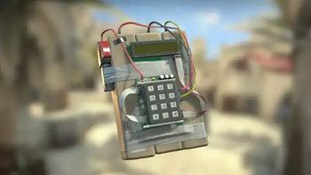
This project brings the iconic C4 explosive from Counter-Strike to life through a custom 3D-printed model and a microcontroller-based embedded system. Powered by FreeRTOS on a PSoC 5LP, the system accurately replicates the game's countdown logic, interactive mechanics, and high-tension audio-visual feedback.
Core Interactive Mechanics
- Arming Sequence: Exclusive to the Terrorist role, players must toggle the [Fire Button] and enter the classic security code 7355608 on the keypad to arm the device.
- Detonation Countdown: Once armed, a 40-second timer begins. The microcontroller drives a buzzer and a red LED, increasing the frequency of the beeps and flashes as detonation nears to simulate rising tension.
- Dynamic Defusal System: Players can intervene to halt the countdown. Holding # initiates a standard 10-second defusal, while holding * simulates having a defuse kit for a rapid 5-second defusal. If the timer reaches zero before the defusal is complete, the bomb "explodes."
- System Reset: After a detonation event, the [Fire Button] must be toggled off and then back on to reset the state and allow a new arming cycle.
Hardware & Technical Highlights
- Hardware Architecture: Utilizes the PSoC 5LP microcontroller as the core to handle complex input logic and precise timing operations.
- Real-Time Operating System: Integrates FreeRTOS to ensure real-time responsiveness and stability for matrix keypad scanning, countdown execution, and synchronized audio/visual outputs.
- Mechanical Design: Housed within a custom 3D-printed shell, seamlessly blending the electronic components into a realistic, interactive physical prop.
1. Introduction & Objectives
1. Introduction & Objectives
1.1 Introduction
This project builds a fully functional CS:GO-style C4 bomb prop around the Cypress/Infineon PSoC 5LP (CY8CKIT-059 kit, CY8C5888LTI-LP097). Behind the playful exterior, the prop is a serious, production-grade exercise in embedded system design: it combines a real-time operating system, three different serial buses, DMA-driven audio streaming from a FAT-formatted SD card, and a carefully choreographed user interface into one coherent firmware architecture.
A game prop turns out to be an ideal teaching vehicle. The requirements are strict enough to be realistic — audio must never stutter, the countdown must never drift, a key press must never be missed — yet the system is small enough that a designer can hold the entire architecture in their head. Every classic embedded-systems problem appears here in miniature: concurrency, shared-resource arbitration, real-time data pipelines, hardware/software co-design in PSoC Creator, and the kind of subtle timing bugs that only reveal themselves on real hardware.
The finished device behaves as follows. When the operator flips the power switch, the character LCD greets the user and a green LED "breathes" softly. Entering the correct 7-digit code arms the bomb: the display clears, a + marker sweeps back and forth across the screen, a red LED flashes in step with an accelerating three-stage beep pattern, and a 40-second countdown begins. A defender may press and hold a defuse key — 10 seconds bare-handed, or 5 seconds with the "defuse kit" key — while the countdown continues mercilessly underneath. Whichever timer expires first decides the outcome: a triumphant DEFUSED message, or a two-stage explosion sound effect streamed from the SD card through an I2S power amplifier.
1.2 Learning Objectives
The project is written for designers who already know C and have basic microcontroller experience, and who want to move from bare-metal super-loops to a professionally structured RTOS application. Working through the design, a designer will learn to:
- Architect a FreeRTOS application — decompose a specification into eight cooperating tasks, choose sensible priorities, and coordinate them with queues, mutexes, semaphores, and event groups instead of global flags.
- Build a real-time audio pipeline — implement the classic producer/consumer pattern with a zero-copy buffer pool: one task reads WAV data from an SD card through FatFs while another feeds the I2S transmitter by DMA, with an abort mechanism that can cut a sound off cleanly mid-stream.
- Drive three serial buses concurrently — I2C (character LCD on a PCF8574 backpack), SPI (SD card in SPI mode, including the raw SD initialization command sequence), and I2S (MAX98357A class-D amplifier) — each protected by its own mutex.
- Use PSoC-specific hardware resources — UDB PWM blocks for tone generation and a breathing LED, a control register gating an RGB LED, a DMA channel with terminal-output interrupt, and the PSoC Creator clock tree (including a real static-timing-analysis violation and its fix).
- Scan a matrix keypad correctly — open-drain row driving with pull-down columns, whole-map debouncing, edge detection for key events, and live key-state publication for press-and-hold gestures.
- Debug like a professional — the report documents every real failure encountered during development (a tick-rate truncation that swallowed LCD characters, an SPI buffer setting that silently starved the whole scheduler, an unpatched interrupt vector table that froze the RTOS at startup) together with the diagnostic path that led to each root cause.
1.3 Functional Specification Summary
- Power control: an external active-low power switch gates the whole user experience; the LCD backlight and all indicators shut down when it is off, while a green LED breathes in standby.
- Code entry: a 4×3 matrix keypad feeds a 7-digit entry field rendered as "- - - - - - -" on a 1×16 character LCD; # clears the attempt and * deletes the last digit. The first key press after each power-up triggers a one-shot initialization sound.
- Arming: the correct code (7355608) starts a 40-second countdown with a three-stage beep cadence (1 Hz → 2 Hz → an exponential-style ramp in the final five seconds), a synchronized red LED, and a bouncing + marker whose speed follows the beep rate.
- Defusing: holding # (10 s) or * (5 s) for one second first enters defuse mode and starts a defusing sound effect; releasing the key aborts both. The countdown keeps running — if it reaches zero mid-attempt, the bomb still detonates.
- Outcomes: success shows ---DEFUSED--- and plays a completion sound; detonation shows ---EXPLODED--- and plays a two-stage explosion sequence. Either way, the system stays down until the power switch is cycled.
- Audio: all sound effects are 16 kHz / 16-bit / mono PCM WAV files streamed from a FAT32 microSD card over SPI and played through an I2S amplifier; short beeps remain on a hardware PWM channel driving a passive buzzer.
- Extras: a hidden backdoor code — left undocumented here as an easter egg for careful readers of the source — triggers an immediate 5-second escalation and detonation, and the on-board push button doubles as an audio-path test trigger.
1.4 Document Roadmap
This report is published as a three-part series. Part 1 (this article) proceeds from the outside in: the system overview, the bill of materials, the hardware design with schematics, and the complete PSoC Creator TopDesign configuration, including clocking and interrupt priorities. Part 2 presents the software architecture — the FreeRTOS task set, the SD-to-I2S audio pipeline, the operating principles behind the countdown and defuse logic, and selected implementation highlights. Part 3 collects the troubleshooting case studies encountered on real hardware, the test results, future work, and the source-code downloads.
2. System Overview
2. System Overview
2.1 System Block Diagram
Figure 2-1 shows the system at a glance. The PSoC 5LP sits at the center; everything the user sees, hears, or touches connects to it over one of three serial buses or plain GPIO. The diagram is organized so that human inputs enter from the left, indications and sound leave to the right, and bulk storage hangs below — the same left-to-right direction in which data actually flows through the firmware.
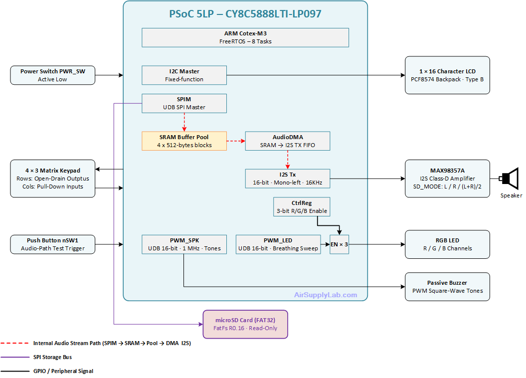
Figure 2-1: System Block Diagram
2.2 Subsystem Summary
| Subsystem | Hardware | Bus / Signal | Owning task(s) |
|---|---|---|---|
| Power & session control | PWR_SW switch | GPIO (debounced) | PowerTask |
| Code entry | 4×3 matrix keypad | GPIO scan | KeypadScanTask → KeypadTask |
| Display | 1×16 LCD, PCF8574 backpack | I2C | PowerTask / KeypadTask / CountdownTask |
| Countdown & defuse logic | — (pure firmware) | — | CountdownTask |
| Tone generation | Passive buzzer, PWM_SPK | PWM square wave | CountdownTask |
| Status lighting | RGB LED + PWM_LED + CtrlReg | Gated PWM | LedBreathTask / CountdownTask |
| Sound-effect playback | microSD + MAX98357A | SPI → DMA → I2S | AudioReadTask → AudioPlayTask |
| Bench test aid | nSW1 push button | GPIO | TestButtonTask |
2.3 Data-Flow Overview
Two largely independent flows run through the system, meeting only at the event group that broadcasts the machine state.
Control flow (left to right). KeypadScanTask sweeps the matrix every 20 ms, debounces the entire keymap, and emits exactly one event per key press into a queue; it also publishes the currently held key for press-and-hold detection. KeypadTask consumes those events, renders the entry field on the LCD, and judges each complete 7-digit attempt. A correct code raises an event-group bit; CountdownTask wakes, takes ownership of the LCD, buzzer, and red LED, and runs the countdown/defuse state machine. PowerTask supervises everything: flipping PWR_SW off clears the state bits, and every task returns to a safe idle.
Audio flow (top to bottom, then out). Any task may request a sound by name. AudioReadTask opens the WAV file on the SD card via FatFs, validates the format, and fills 512-byte blocks from a shared pool; AudioPlayTask arms one DMA transfer per block into the I2S TX FIFO and recycles each block as it empties. Because only descriptors travel through the queues, the PCM data itself is never copied — a zero-copy pipeline that keeps SD-card read jitter from reaching the speaker. An abort mechanism lets the state machine cut a playing sound cleanly (for example, when a defuse attempt is released halfway).
2.4 Operating States at a Glance
The full state machine is developed in Part 2; for orientation, the system passes through five macroscopic states: Standby (power switch off; green LED breathing, LCD dark) → Entry (LCD shows the dash field, digits accepted) → Armed (40-second countdown, staged beeps, marker animation) → optionally Defusing (a hold-key overlay running on top of the still-live countdown) → a terminal Outcome (DEFUSED or EXPLODED, with its sound sequence), which persists until the power switch is cycled.
3. Component Requirements
3. Component Requirements
3.1 Bill of Materials
Table 3-1 lists everything needed to build the prop. All parts are inexpensive, widely available modules; nothing requires custom PCB work — the whole system assembles on a breadboard or a piece of perfboard.
Table 3-1: Bill of materials
| # | Item | Qty | Key specifications | Role in the system |
|---|---|---|---|---|
| 1 | CY8CKIT-059 PSoC 5LP Prototyping Kit | 1 | CY8C5888LTI-LP097 · ARM Cortex-M3 @ up to 80 MHz · 256 KB flash / 64 KB SRAM · on-board KitProg programmer | Host MCU; runs FreeRTOS and all peripherals |
| 2 | 1×16 character LCD with PCF8574 I2C backpack | 1 | HD44780-compatible · 4-bit mode via PCF8574 · I2C address 0x27 · "Type B" internal 2×8 addressing | Code entry display, countdown marker, outcome messages |
| 3 | 4×3 matrix keypad | 1 | 12 keys (0–9, *, #) · membrane or tactile · 7-pin header | Code entry and defuse hold-keys |
| 4 | Passive buzzer (magnetic transducer) | 1 | No internal oscillator · resonant peak typically 2–4 kHz | Countdown beeps driven by a PWM square wave |
| 5 | RGB LED (common-cathode) + 3 series resistors | 1 | 5 mm or 10 mm · ~220–470 Ω per channel | Green breathing (standby/entry) and red countdown flash |
| 6 | MAX98357A I2S amplifier breakout | 1 | 3 W class-D · standard I2S slave · SD_MODE channel-select pin | Plays WAV sound effects streamed from the SD card |
| 7 | Speaker | 1 | 4 Ω or 8 Ω, 2–3 W | Sound-effect output |
| 8 | microSD card reader breakout (SPI) | 1 | Level-appropriate module (see note in 3.2) · SPI-mode wiring | Stores the WAV sound bank |
| 9 | microSD card | 1 | ≤ 32 GB, formatted FAT32 | Sound-bank medium |
| 10 | Toggle or slide switch (power switch) | 1 | SPST, wired active-low | Session control: arms and resets the whole experience |
| 11 | Breadboard, jumper wires, misc. | — | — | Assembly |
3.2 Component Selection Notes
Each part was chosen for a specific technical reason; understanding these choices is itself part of the lesson.
PSoC 5LP (CY8CKIT-059). The star of the show. Beyond the Cortex-M3, the PSoC's programmable UDB fabric supplies the two 16-bit PWMs, the SPI master, the I2S transmitter, the control register, and the DMA channel — all wired graphically in TopDesign rather than fought over as fixed peripherals. The 64 KB of SRAM comfortably hosts a 20 KB FreeRTOS heap plus the audio buffer pool. The kit's snap-off KitProg section programs and debugs the target over USB, so no external programmer is needed.
1×16 character LCD, PCF8574 backpack. The I2C backpack reduces the LCD's 4-bit parallel interface to two wires, which matters on a pin-hungry design. Note that many 1×16 modules are internally organized into two rows of eight ("Type B"): columns 0–7 map to DDRAM 0x00–0x07, while columns 8–15 map to DDRAM 0x40–0x47. The driver in this project handles the translation transparently; Part 2 covers the details.
Passive buzzer. "Passive" means the buzzer has no internal oscillator — it sounds only while an external square wave drives it, and the drive frequency is the pitch. That is exactly what the PWM tone generator needs.
MAX98357A. A remarkably designer-friendly part: it accepts standard I2S with no configuration bus at all (no I2C/SPI control registers), integrates a 3 W class-D output stage, and selects which channel it reproduces with a single resistor-strapped pin (SD_MODE). Since this project transmits mono on the left channel, set SD_MODE to left to get full volume; the (L+R)/2 default also works, just 6 dB quieter.
microSD in SPI mode. Every SD card speaks a simple SPI-mode protocol in addition to its native bus, which lets a plain SPI master and the FatFs library read a standard FAT32 file system — no licensing, no 4-bit SD host controller required. Choose a breakout that matches your I/O voltage: on a 5 V PSoC supply, use a module with an on-board level shifter and regulator; modules without one are meant for 3.3 V systems.
RGB LED behind gated PWM. A single PWM (PWM_LED) generates the brightness waveform, and a 3-bit control register enables it onto the R, G, or B channel through buffer gates in the UDB fabric. One PWM thus serves three LEDs — a small illustration of how PSoC lets you use logic rather than peripherals.
3.3 SD Card and Sound-Bank Preparation
The audio pipeline is deliberately minimal — it streams raw PCM straight from the file into the I2S FIFO with zero CPU processing — so the files must match the hardware configuration exactly:
- Format: WAV, uncompressed PCM (audioFormat = 1)
- Sample rate: 16 000 Hz (set by the I2S input clock: 2.048 MHz ÷ 128)
- Resolution/channels: 16-bit, mono
- File names: 8.3 format, upper case (e.g., C4INIT.WAV) — long-file-name support is compiled out of FatFs to save RAM
- Card format: FAT32
Any audio editor or ffmpeg converts arbitrary source material in one step:
ffmpeg -i source.mp3 -ac 1 -ar 16000 -sample_fmt s16 C4INIT.WAV3.4 Development Tools
- PSoC Creator 4.4 — schematic entry (TopDesign), component configuration, code generation, build, and debug.
- FreeRTOS kernel sources (ARM_CM3 GCC port) added to the project.
- FatFs R0.16 by ChaN — the FAT file-system module; download the official archive from elm-chan.org/fsw/ff/ and add ff.c, ff.h, ffconf.h, and diskio.h to the project (the diskio.c glue layer is provided in this series).
- An audio converter (ffmpeg or Audacity) for preparing the sound bank.
4. Hardware Design & Schematics
4. Hardware Design & Schematics
4.1 Pin Assignment
Table 4-1 is the complete pin map of the design, taken directly from the project's .cydwr Pins editor. The drive mode column is not a formality — three of the subsystems in this design only work because of a deliberately chosen drive mode, as the following subsections explain.
Table 4-1: Pin assignment and drive modes
| Signal | Port pin | Direction | Drive mode | Purpose |
|---|---|---|---|---|
| I2C_SCL / I2C_SDA | P1[6] / P1[7] | bidir | Open drain (fixed-function I2C) | LCD backpack, addr 0x27 |
| Keypad_Rows[3:0] | P12[3:0] | out | Open drain, drives high | Matrix row select |
| Keypad_Cols[2:0] | P12[6:4] | in | Resistive pull-down | Matrix column sense |
| PWR_SW | P2[0] | in | Resistive pull-up | Power switch (active low) |
| LED1 | P2[1] | out | Strong drive | On-board LED, PWM monitor |
| nSW1 | P2[2] | in | Resistive pull-up | On-board button, audio test |
| I2S_SCK | P2[5] | out | Strong drive | I2S bit clock (2.048 MHz) |
| I2S_SDO | P2[6] | out | Strong drive | I2S serial data |
| I2S_WS | P2[7] | out | Strong drive | I2S word select (16 kHz frame) |
| BUZZER | P3[0] | out | Strong drive | PWM_SPK square wave |
| SPI_SS | P3[4] | out | Strong drive (GPIO, not SPIM SS) | SD card chip select |
| SPI_SCLK | P3[5] | out | Strong drive | SD SPI clock |
| SPI_MOSI | P3[6] | out | Strong drive | SD SPI data out |
| SPI_MISO | P3[7] | in | High-impedance digital | SD SPI data in |
| LED_RGB[2:0] | P0[7:5] | out | Strong drive | Gated PWM to R / G / B |
4.2 Keypad Matrix Circuit
The 4×3 keypad is a bare switch matrix: pressing a key connects one row wire to one column wire, nothing more. The electrical scheme chosen here — open-drain rows that drive high, columns with pull-downs — makes the scan both safe and simple.
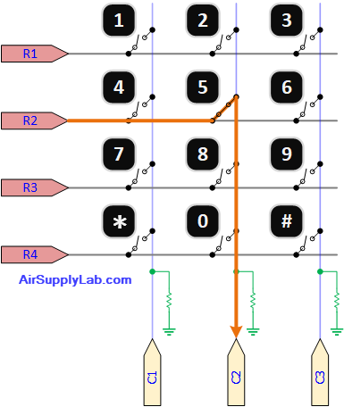
Figure 4-1: Keypad matrix schematic
How the scan works. The firmware selects exactly one row at a time by writing a one-hot mask: the selected row is actively driven high, while every other row is written 0, which in this drive mode means high impedance — electrically absent. The three columns are then read: an idle column is held at 0 by its pull-down; a column reads 1 only if a key connects it to the currently driven row. Row/column intersection identifies the key.
Two electrical details deserve attention:
- Why open-drain? If two keys in the same column are pressed while rows are push-pull driven, a driven-high row and a driven-low row would be shorted together through the switches. With open-drain-high rows, non-selected rows float rather than fight — the matrix is short-circuit-proof by construction.
- Settle time. A column's rising edge is powered by the row driver, but its capacitance was previously held low through the pull-down; after selecting a row, the firmware waits ~20 µs before sampling so the column voltage settles. This constant lives in the scanner and can be raised for long, high-capacitance cable runs.
4.3 RGB LED Gating
One PWM serves all three LED colors. PWM_LED (1 MHz clock, period 1000 → a flicker-free 1 kHz PWM with 0.1 % duty resolution) generates a single brightness waveform; inside the UDB fabric, it fans out to three AND-style buffer gates, each enabled by one bit of the 3-bit control register CtrlReg (bit 0 = R, bit 1 = G, bit 2 = B). The gated outputs leave on P0[7:5] through per-channel series resistors to a common-cathode RGB LED.
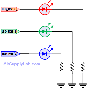
Figure 4-2: PWM gating schematic
The division of labor is clear: software sets the PWM compare value to create effects (the breathing ramp, or parking the duty at 100% during the countdown so the red channel flashes at full brightness), while the color lit is a one-bit register write. Because two different tasks own those two halves at different times, the register is wrapped in a read-modify-write mutex — a story for Part 2.
4.4 Audio Output Path
The I2S connection to the MAX98357A is three wires plus power:
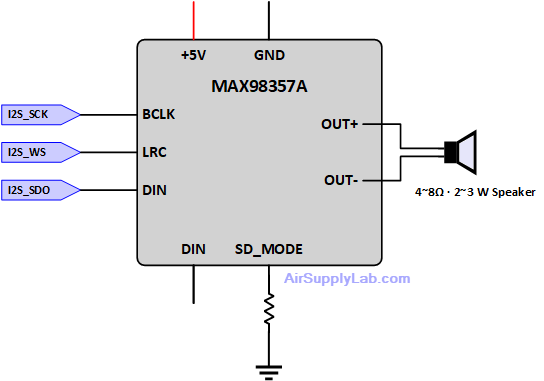
Figure 4-3: Audio path wiring
The amplifier is an I2S slave with no control bus: it locks onto whatever the PSoC transmits. The frame timing (64-bit word-select period) and the 2.048 MHz bit clock together set the sample rate to 16 kHz; the firmware transmits 16-bit mono on the left channel. All of that is configured in TopDesign — Section 5 shows the exact component settings, including one checkbox (Tx byte swap) that stands between you and pure noise.
4.5 SD Card SPI Wiring
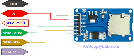
Figure 4-4: SD card wiring
The one decision on this page that regularly bites designers is the chip select. It is tempting to let the SPI master's hardware SS pin handle CS "for free" — but SD-card commands are multi-byte transactions: a command frame, response bytes, wait states, and possibly a 512-byte data block with its token and CRC must all occur under one continuous CS assertion. Hardware SS on most SPI blocks releases the line between bytes or between FIFO batches, which the card interprets as end-of-transaction, and initialization fails in maddeningly intermittent ways. A GPIO under explicit firmware control (assert, run the whole transaction, deassert) removes the entire failure class.
5. PSoC Creator TopDesign Configuration
5. PSoC Creator TopDesign Configuration
Everything in Section 4 was wiring; this section is the other half of PSoC hardware design — the components placed on TopDesign.cysch and their parameters. Several of these settings look innocent but are load-bearing: three of them, mis-set, produce failures ranging from pure noise to a completely frozen scheduler. Each is called out below.
5.1 TopDesign at a Glance
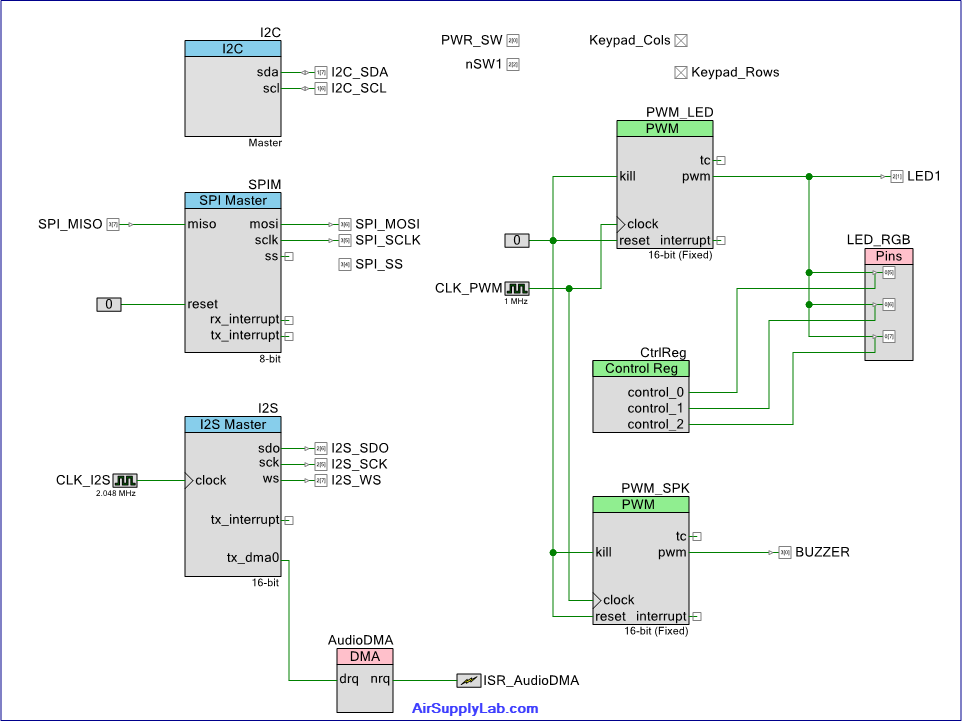
Figure 5-1: TopDesign.cysch overview
The design places seven components plus the pins from Table 4-1:
- I2C — fixed-function I2C master (LCD)
- SPIM — UDB SPI master (SD card)
- I2S — I2S transmitter (MAX98357A)
- AudioDMA + ISR_AudioDMA — DMA channel and its completion interrupt
- PWM_SPK — buzzer tone generator
- PWM_LED — LED brightness sweep
- CtrlReg — 3-bit control register gating the RGB channels (Figure 4-2)
5.2 Component Parameters
Table 5-1: Component configuration summary
| Component | Parameter | Value | Why it matters |
|---|---|---|---|
| I2C (fixed-function) | Mode | Master | LCD backpack is a slave at 0x27 |
| Data rate | 100 kbps | Standard-mode; PCF8574 maximum | |
| SPIM | Mode | CPOL = 0, CPHA = 0 | SD SPI-mode requirement |
| Clock selection | External (CLK_SPIM) | Let's firmware retune the SPI speed at runtime: 400 kHz for SD init, 4 MHz for data — see §5.3 | |
| RX / TX Buffer Size | 4 / 4 | Hardware FIFO only — see the caution below | |
| Shift direction | MSB first | SD protocol is MSB-first | |
| I2S | Direction | Tx only | Playback-only design |
| Data bits | 16 | Matches the 16-bit PCM WAV files | |
| Word select period | 64 | With the 2.048 MHz input clock → 16 kHz sample rate | |
| Tx channels | Mono left | Mono WAV data maps 1:1 to the FIFO | |
| Tx byte swap | Enabled | WAV is little-endian; the FIFO wants MSB first — see below | |
| AudioDMA | Bytes/request per burst | 1 / 1 | drq level paces one byte per FIFO slot |
| Hardware request | Level | tx_dma0 is a level signal ("FIFO not full") | |
| TD flags | TERMOUT enabled, increment source | TERMOUT fires nrq at block completion — without it the completion interrupt never occurs | |
| Destination | I2S_TX_CH0_F0_PTR | Channel-0 TX FIFO register | |
| ISR_AudioDMA | Interrupt type | Rising edge | nrq is a short pulse, not a level |
| Priority | 3 | See Table 5-3 | |
| PWM_SPK | Resolution/clock | 16-bit / 1 MHz | Period = 1 MHz ÷ tone; 2 kHz tone → period 500 (would overflow an 8-bit PWM) |
| Started at boot? | No | Started on demand by the firmware; starting it in the init buzzes at power-up | |
| PWM_LED | Resolution/clock/period | 16-bit / 1 MHz / 1000 | 1 kHz flicker-free PWM, 0.1 % duty steps |
| CtrlReg | Width | 3 bits | bit 0 = R, bit 1 = G, bit 2 = B |
5.3 Clock Tree
Table 5-2: Clock plan
| Clock | Frequency | Derivation | Consumer |
|---|---|---|---|
| PLL_OUT → MASTER_CLK → BUS_CLK | 48 MHz | IMO 3 MHz × PLL | CPU, UDB fabric, FreeRTOS tick base |
| CLK_I2S | 2.048 MHz | ÷ from master | I2S (→ 16 kHz sample rate: 2.048 MHz ÷ 64 ÷ 2) |
| CLK_PWM | 1 MHz | 48 MHz ÷ 48 (exact) | PWM_SPK and PWM_LED |
| CLK_SPIM (SPIM external clock) | 800 kHz → 8 MHz (runtime) | 48 MHz ÷ 60, retuned to ÷ 6 by firmware | SD SPI — SCLK = input ÷ 2: 400 kHz during init, 4 MHz for data |
One clock, two speeds. The SD specification requires the entire initialization sequence to run at 100–400 kHz; only after the card reports ready may the host raise the clock. Rather than compromising on a single frequency, the SPIM uses an external clock (CLK_SPIM, set to 800 kHz in the schematic) and diskio.c retunes its divider at runtime: CLK_SPIM_SetDividerValue(60) before the init sequence (SCLK 400 kHz), CLK_SPIM_SetDividerValue(6) once the card is identified (SCLK 4 MHz). The switch matters quantitatively: at 400 kHz, the bus delivers barely 40 KB/s after protocol overhead, against the audio pipeline's 32 KB/s sustained appetite — a margin thin enough to starve playback. At 4 MHz, the margin is roughly 15×. Two details make the switching robust: the slow speed is forced at every disk_initialize() entry (so a retry after a card swap never inherits the fast clock), and the divider is only ever changed while CS is deasserted, so no transfer can straddle the glitch.
Why 48 MHz and not the maximum? This design originally ran BUS_CLK at 74 MHz — and the build's Static Timing Analysis reported a setup violation with −4.45 ns of slack: the UDB fabric containing the PWMs, the SPI master, the I2S shifter, and the control register could only close timing up to 55.65 MHz. A timing violation is not a warning to dismiss; it means register-to-register paths may mis-capture, producing intermittent, temperature-dependent corruption — the kind that works on the bench and fails in the field. Dropping the master clock to 48 MHz (comfortably below the fabric's ceiling and exactly dividing both 1 MHz and 2 MHz peripheral clocks) cleared every violation with zero functional cost: nothing in this system needs more CPU.
5.4 Interrupt Configuration
FreeRTOS on Cortex-M3 imposes one iron rule: any interrupt handler that calls a ...FromISR() API must run at a priority numerically greater than or equal to configMAX_SYSCALL_INTERRUPT_PRIORITY. This project sets that threshold at priority 2, and the kernel itself (SysTick/PendSV) at the lowest priority 7:
#define configPRIO_BITS                       3
#define configKERNEL_INTERRUPT_PRIORITY       ( 7 << 5 )   /* 0xE0 */
#define configMAX_SYSCALL_INTERRUPT_PRIORITY  ( 2 << 5 )   /* 0x40 */
Table 5-3: Interrupt priority plan (PSoC 5LP: 0 = highest, 7 = lowest)
| Interrupt source | Priority | Calls FreeRTOS APIs? | Notes |
|---|---|---|---|
| ISR_AudioDMA | 3 | Yes (xSemaphoreGiveFromISR) | Must be ≥ 2; kept urgent for audio latency |
| I2C internal | 5 | No | Component-managed; polled driver |
| SysTick / PendSV / SVC | 7 | — (kernel) | Always the lowest priority |
Note that PSoC Creator's interrupt editor takes the raw 0–7 values from the table, while FreeRTOSConfig.h takes the same values shifted left by 5 (the priority field occupies the top 3 bits of an 8-bit register). Keeping the two representations consistent is the designer's job; get it wrong in the dangerous direction (an ISR more urgent than the syscall threshold calling a FromISR function) and the scheduler's internal state corrupts in ways that surface far from the cause.
5.5 Part 1 Summary
At this point, the hardware story is complete: every part on the bench (Section 3), every wire and drive mode (Section 4), and every component parameter, clock, and interrupt priority (this section) has a documented reason. The prop, however, is still silent and dark — all of its behavior lives in firmware. Part 2 picks up there: how eight FreeRTOS tasks divide the specification among themselves, how the SD-to-I2S audio pipeline moves sound without copying it, and how the countdown, defuse, and explosion logic is orchestrated in a single unified engine loop.
6. Software Architecture
6. Software Architecture
Part 1 of this series covered the hardware: the bill of materials, the wiring, and every TopDesign parameter. Part 2 is the firmware. This section presents the architecture — how the specification decomposes into FreeRTOS tasks, how those tasks communicate, and how the audio pipeline streams sound from an SD card to an I2S amplifier without ever copying a sample.
6.1 The Task Set
The whole specification factors into eight tasks, each owning one concern and one set of hardware. The decomposition rule used throughout: a task owns a resource (a bus, a peripheral, a data stream), never a feature — features emerge from tasks cooperating through queues and events.
Table 6-1: FreeRTOS task set
| Task | Priority | Stack (words) | Responsibility | Blocks on |
|---|---|---|---|---|
| AudioPlayTask | +4 (highest) | min + 192 | Feed the I2S FIFO by DMA; recycle emptied buffers | ready-buffer queue, DMA-done semaphore |
| PowerTask | +3 | min + 64 | Debounce PWR_SW; own the power state transition and the LCD lifecycle | 20 ms poll |
| CountdownTask | +3 | min + 96 | The armed state machine: staged beeps, marker, defuse tracking, outcomes | event group (arm bits) |
| AudioReadTask | +2 | min + 512 | Mount FatFs, parse WAV headers, fill PCM blocks from the SD card | request queue, free-buffer queue |
| KeypadTask | +2 | min + 256 | Consume key events; render entry; judge the code | key queue |
| KeypadScanTask | +2 | min + 64 | Scan the matrix, debounce, emit press edges, publish held-key state | 20 ms poll |
| LedBreathTask | +1 | min + 32 | Green-LED breathing; pause on key activity; park PWM when armed | 10 ms poll |
| TestButtonTask | +1 | min + 32 | nSW1 hold-5-s audio test trigger | 50 ms poll |
Three priority decisions carry the architecture:
- AudioPlayTask is alone at the top. It is the only task with a hard real-time deadline: if the I2S FIFO ever starves, the listener hears it. Its work per wake-up is tiny (re-arm one DMA descriptor), so giving it the highest priority costs the rest of the system almost nothing.
- PowerTask outranks the workers. The power switch is the user's ultimate reset lever; it must respond even if a storage or audio task misbehaves. This placement was learned the hard way — an early revision put PowerTask at the bottom, and a hung SPI busy-wait at a higher priority made the whole prop unresponsive, power switch included. The full story is a Part 3 case study.
- AudioReadTask gets the big stack. FatFs calls nest deeply and keep sector-sized workings on the stack; 512 extra words is the price of file-system access. Every figure in the stack column was later verified against uxTaskGetStackHighWaterMark().
Figure 6-1: Task-and-communication diagram
Drawing plan: eight rounded task boxes arranged in three bands by priority (top band: AudioPlayTask; middle: PowerTask, CountdownTask, then AudioReadTask, KeypadTask, KeypadScanTask; bottom: LedBreathTask, TestButtonTask). Between them, the communication objects are drawn as distinct shapes: queues as open-ended rectangles with slot ticks (xKeyQueue between the two keypad tasks; xAudioReqQ into AudioReadTask; the xFreeBufQ / xReadyBufQ pair forming a circular loop between AudioReadTask and AudioPlayTask around a cylinder labeled "gAudioPool 4×512 B"); the event group as a horizontal bit-field strip in the center with radiating dashed lines to every task that waits on or sets each bit; mutexes as small padlock icons attached to three shared-resource callouts (I2C bus, SPI bus, CtrlReg). One ISR lightning-bolt symbol (AudioDMA_Done_ISR) giving xI2sDoneSem into AudioPlayTask.
6.2 Communication Objects
No task calls another; every interaction crosses one of these objects. That single discipline is what makes the system testable one piece at a time.
Table 6-2: Queues and semaphores
| Object | Type/depth | Producer → Consumer | Payload |
|---|---|---|---|
| xKeyQueue | Queue, 8 | KeypadScanTask → KeypadTask | ASCII key code (uint8_t) |
| xAudioReqQ | Queue, 2 | anyone → AudioReadTask | file name (AudioReq_t) |
| xFreeBufQ | Queue, 4 | AudioPlayTask → AudioReadTask | empty block descriptor |
| xReadyBufQ | Queue, 4 | AudioReadTask → AudioPlayTask | filled block descriptor |
| xI2sDoneSem | Binary semaphore | DMA ISR → AudioPlayTask | block-completion signal |
| xI2CMutex / xSpiMutex | Mutex | — | bus ownership (LCD; SD card) |
| xCtrlRegMutex | Mutex | — | read-modify-write guard for the RGB register |
Table 6-3: Event-group bits (xSysEvents) — the system's broadcast state
| Bit | Name | Set by | Cleared by | Meaning |
|---|---|---|---|---|
| 0 | EVT_POWER_ON | PowerTask | PowerTask | Session live; every task gates on it |
| 1 | EVT_COUNTDOWN | KeypadTask | PowerTask (power-off) | Correct code entered; bomb armed |
| 2 | EVT_PLAY_AUDIO | AudioReadTask | AudioReadTask | A stream is playing (used by blocking waits) |
| 3 | EVT_INSTANT_BOOM | KeypadTask | PowerTask | The easter-egg code fired |
| 4 | EVT_AUDIO_ABORT | Audio_Abort() | AudioReadTask (see 6.3) | Cut the current stream |
6.3 The Audio Pipeline
The most instructive subsystem in the project. The requirement sounds simple — "play WAV files from the SD card" — but hides three hard sub-problems: SD reads have unpredictable latency; the I2S consumes samples at an inflexible 32 KB/s; and the state machine must be able to cut a sound off (a released defuse key) without corrupting whatever plays next.
The zero-copy buffer pool. Four 512-byte blocks live in static RAM. Two queues circulate descriptors (pointer + length) between the producer and consumer:
typedef struct
{
    uint8_t  *pData;       /* points into gAudioPool[]; NULL == end-of-stream */
    uint16_t  length;      /* valid bytes                                     */
} AudioBlock_t;
AudioReadTask takes an empty descriptor from xFreeBufQ, fills the block via f_read(), and sends it to xReadyBufQ. AudioPlayTask takes it, arms one DMA transfer into the I2S FIFO, sleeps on the DMA-done semaphore, and returns the descriptor to xFreeBufQ. The PCM data never moves in software; only 6-byte descriptors travel. Four blocks ≈ 64 ms of audio in flight — enough slack to absorb any single SD-card read stall.
End-of-stream is in-band. When the file ends (or aborts), the reader posts a descriptor with pData == NULL. The player treats it as "stop after what is queued drains" — no side-channel flag, no polling, no race about who noticed the end first.
Aborting a stream — and the sticky-abort trap. Audio_Abort() sets EVT_AUDIO_ABORT and flushes any queued requests; the reader checks the bit between blocks and closes the file early. The subtle question is who clears the bit, and when. The answer that survived debugging: the reader clears it immediately after accepting a new request — not when the abort is serviced, and never the caller.
/* AudioReadTask main loop (shape) */
if (xQueueReceive(xAudioReqQ, &req, portMAX_DELAY) == pdTRUE)
{
    /* v2 fix: a stale abort must not kill THIS new request */
    xEventGroupClearBits(xSysEvents, EVT_AUDIO_ABORT);
    ...open, parse, stream blocks, checking the bit between blocks...
}Blocking playback for sequences. Outcome sounds must play in order (explosion = two files back-to-back), so the audio module offers Audio_PlayBlocking(name, maxMs): wait for any current stream to end, request, wait for start, wait for finish — every wait is bounded, so a missing file can never hang the state machine.
[Figure 6-2: Audio pipeline diagram — drawing plan]
Drawing plan: a circular flow. Left: the SD card feeding AudioReadTask (annotated "FatFs · WAV parse · abort check between blocks"). Center: the two queues drawn as opposing conveyor belts — xReadyBufQ carrying filled blocks rightward on top, xFreeBufQ returning empties leftward below — around a static RAM cylinder "gAudioPool 4 × 512 B". Right: AudioPlayTask arming the AudioDMA block into the I2S FIFO, with the DMA-done ISR looping back via xI2sDoneSem. A red scissor icon on the reader labeled EVT_AUDIO_ABORT, and a NULL-descriptor tag riding the top belt labeled "EOS marker".
6.4 RTOS Bring-Up on PSoC 5LP
Part 1 ended on a cliffhanger: three FreeRTOS exception handlers must be installed by hand. On PSoC 5LP, cy_boot relocates the vector table into RAM and fills it with default handlers; the SVC, PendSV, and SysTick entries that FreeRTOS depends on are not wired to the kernel. Patch them before starting the scheduler:
extern void vPortSVCHandler( void );
extern void xPortPendSVHandler( void );
extern void xPortSysTickHandler( void );
extern cyisraddress CyRamVectors[];

void FreeRTOS_Init( void )
{
    CyRamVectors[ 11 ] = ( cyisraddress ) vPortSVCHandler;     /* SVC     */
    CyRamVectors[ 14 ] = ( cyisraddress ) xPortPendSVHandler;  /* PendSV  */
    CyRamVectors[ 15 ] = ( cyisraddress ) xPortSysTickHandler; /* SysTick */
}
Miss this and vTaskStartScheduler() issues its first SVC into a default infinite-loop handler: the system freezes with no fault, no assert, no clue. The remaining configuration essentials:
- configTICK_RATE_HZ = 1000 — a 1 ms tick, so every pdMS_TO_TICKS() is exact (a 100 Hz tick truncates small delays to zero; Part 3 shows the LCD bug that caused)
- configTOTAL_HEAP_SIZE = 20 KB (heap_4) — eight tasks + idle/timer + all queues; sized with headroom after an out-of-heap incident
- configCPU_CLOCK_HZ = BCLK__BUS_CLK__HZ — follow the design-wide clock automatically; never hard-code it
- Stack-overflow and malloc-failed hooks enabled, and trapping — loud failures beat silent corruption
6.5 Source-File Map
Table 6-4: Firmware source files
| File | Contents |
|---|---|
| main.c | Hardware init, vector patch, RTOS object + task creation, hooks |
| app_shared.h | Every shared handle, event bit, buffer geometry, WAV sound-bank names |
| powertask.c | PWR_SW debounce, boot splash, power on/off transitions |
| keypadscantask.c | Matrix scan, debounce, edge events, live held-key state |
| keypadtask.c | Entry rendering, code judgment, one-shot init sound |
| countdowntask.c | The armed engine: beeps, marker, defuse tracker, outcomes |
| ledtask.c | Green-LED breathing manager |
| testbuttontask.c | nSW1 hold-to-test trigger |
| Audio.h / AudioReadTask.c | Audio API (request / abort / play-blocking) and the WAV reader |
| audioplaytask.c | DMA feeder and the DMA-done ISR |
| diskio.c | FatFs glue: SD SPI-mode protocol (init, block read) |
| LCD_I2C_PCF8574.c / .h | HD44780 driver over PCF8574, incl. 1×16 Type-B addressing |
| i2c_function.c / .h | Register-oriented I2C read/write primitives |
Section 7 walks through the operating principles built on this skeleton — the state machine, the three-stage cadence math, and the defuse race — and Section 8 closes Part 2 with selected implementation highlights from these files.
7. Operating Principles
7. Operating Principles
Section 6 built the skeleton; this section explains the behavior that runs on it — the state machine, the arithmetic behind the accelerating beeps, the defuse race, and two pieces of display craft that make the prop feel polished.
7.1 The System State Machine
Figure 7-1: System state machine
Drawing plan: five rounded states left to right: Standby (green LED breathing, LCD dark) → Entry (arrow labeled "PWR_SW on / splash, dash field") → Armed (arrow "correct code / clear screen, start 40 s") → two terminal states stacked at right: Defused and Exploded. Draw Defusing not as a fifth sequential state but as a smaller box overlapping Armed's lower edge, connected by a two-way arrow pair ("hold #/* ≥ 1 s" down, "release / Audio_Abort" back up), with its own exit to Defused ("held 5 s / 10 s"). Both Armed and Defusing have arrows to Exploded labeled "elapsed = 40 s — even mid-hold". From both terminal states, one common return arrow sweeps back to Standby labeled "PWR_SW cycle (the only way out)". A dashed easter-egg arrow leaves Entry to a small "Instant Boom" box feeding Exploded. Every arrow label is an event / action pair — the same convention as a Moore FSM diagram.
Two properties of this machine are deliberate and worth internalizing:
- Defusing is an overlay, not a sibling state. The countdown clock, the staged beeps, and the marker animation all continue while a defuse attempt runs. Modeling defuse as a parallel tracker inside the Armed engine (rather than a transition out of it) is what makes the "whichever timer expires first" rule fall out naturally, with no state to restore when the player lets go.
- Terminal states have exactly one exit. After an outcome, no key does anything; only cycling PWR_SW re-arms the machine. PowerTask owns that transition and clears every arm bit, so a half-finished session can never leak into the next one.
7.2 The Three-Stage Beep Cadence
The countdown's tension curve is pure arithmetic. The beep interval is a function of remaining time rem (in ms):
static uint32_t BeatInterval(uint32_t remMs)
{
    if (remMs > 15000u) return 1000u;                    /* stage 1: 1 Hz  */
    if (remMs >  5000u) return  500u;                    /* stage 2: 2 Hz  */
    return 50u + ((remMs * remMs) / 125000u);            /* stage 3: ramp  */
}
Stages 1 and 2 are constants; stage 3 is the interesting one. The design goal is a perceived exponential acceleration over the final five seconds — the classic movie-bomb effect — without floating point or a lookup table. A quadratic does the job:
- At rem = 5000: 50 + 5000²/125000 = 50 + 200 = 250 ms (4 Hz)
- At rem = 2500: 50 + 50 = 100 ms (10 Hz)
- At rem = 0: 50 ms (20 Hz — effectively a buzz)
Because the curve is steepest near zero, each second feels faster than the last — which is exactly how an exponential sounds, even though the formula is polynomial. Note also the deliberate discontinuity at the stage-2/3 boundary: the interval jumps from 500 ms to 250 ms in one beat. That audible "gear change" is the five-second warning.
The beep's ON time is min(interval/2, 60 ms): half-duty at slow rates for a relaxed "tick… tick…", but capped at 60 ms so that even at 20 Hz each blip stays a crisp click instead of merging into a continuous tone.
7.3 The Defuse Race
Defusing is a hold gesture measured against a running clock, with three thresholds in play: 1 s to enter, then 5 s (*, "with kit") or 10 s (#, "bare-handed") to finish — all while the 40-second countdown keeps running. The tracker is a tiny sub-state machine polled every 10 ms slice:
- IDLE → a defuse key appears in gKeypadCurrentKey → PREHOLD, accumulate holdMs.
- PREHOLD: release before 1000 ms → silently back to IDLE (no sound, no penalty — a brushed key is not an attempt). Reach 1000 ms → DEFUSING: play WAV_DEF_START, zero defuseMs, latch the required hold for this key.
- DEFUSING: release or key change → Audio_Abort(), back to IDLE (a new attempt starts from the 1-second gate again). Reach the requirement → DEFUSED.
- At any moment, in any sub-state: elapsed ≥ 40 s → EXPLODED. Holding the key is not a shield.
Who wins an exact tie? With 10 ms polling, both thresholds can cross in the same slice. The loop body evaluates the defuse tracker before incrementing elapsed and re-testing the countdown bound — so a same-slice tie goes to the defender. That is not an accident: the rule is encoded purely by statement order, costs zero code, and matches the game convention that a completed defuse counts even as the timer hits zero. When a race's resolution matters, write down which side wins and make the code's evaluation order say so.
Figure 7-2: Defuse-attempt timing diagram
Drawing plan: a horizontal time axis with four aligned lanes. Lane 1 "key" shows a hold starting at t₀, releasing at t₀+4 s, then a second hold. Lane 2 "tracker state" shows IDLE / PREHOLD (1 s hatched) / DEFUSING, dropping back to IDLE at the release and climbing again on the second hold. Lane 3 "audio" shows C4DISSTR starting at t₀+1 s, a red scissor cut at the release (Audio_Abort), a fresh C4DISSTR on the second attempt, and C4DISFIN at success. Lane 4 "countdown" is a continuous beep train whose pulses visibly tighten (stage transitions marked at rem = 15 s and 5 s), running uninterrupted underneath everything — the visual argument that defusing never pauses the bomb.
7.4 The '+' Marker: Animation Under a Visibility Floor
During the countdown, a + bounces across the seven dash positions (odd columns 1–13) as a visual heartbeat. Its scheduler is one line: hop every max(interval/2, 200 ms) — twice the beep rate, clamped.
The clamp is the design decision. Unclamped, stage 3 would demand a hop every 25 ms: each hop costs two I2C transactions (erase old cell, draw new cell) on a 100 kbps bus shared with nothing else at that moment but budgeted for coexistence, and — more fundamentally — a character that teleports every 25 ms reads as flicker, not motion. 200 ms is roughly the floor at which the eye still tracks discrete character movement as movement. So the marker accelerates honestly through stages 1 and 2 (500 → 250 ms) and then saturates while the beeps keep accelerating underneath — the ear carries the final panic, the eye stays legible. Splitting one "faster!" requirement across two output channels with different perceptual limits is a small but transferable piece of UX engineering.
7.5 The 1×16 "Type B" LCD: One Row That Is Secretly Two
Many inexpensive 1×16 character modules are electrically a 2×8 display laid end to end: columns 0–7 live at DDRAM 0x00–0x07, but columns 8–15 live at 0x40–0x47 — the address range a 16×2 panel uses for its second row. (A "Type A" 1×16 is genuinely linear, 0x00–0x0F, and wants 1-line mode; Type B must be initialized in 2-line mode, N = 1, despite being physically one row.)
The driver hides the seam behind the normal API, and it takes two cooperating fixes because there are two ways to reach column 8:
Random access — LCD_Position() translates the column before issuing Set-DDRAM:
if (sLcdType == LCD_TYPE_1X16_B && row == 0u) {
    if (col < 8u) sendCmd(HD_SET_DDRAM | col);
    else          sendCmd(HD_SET_DDRAM | (0x40u + (col - 8u)));
}
Sequential streaming — LCD_PutChar() tracks the cursor and jumps the seam mid-string, so LCD_PrintString() crosses column 8 transparently:
sendData((uint8_t)c);
sCursorCol++;
if (sLcdType == LCD_TYPE_1X16_B && sCursorCol == 8u) {
    sendCmd(HD_SET_DDRAM | 0x40u);      /* hop to the right half */
}
Either fix alone leaves a hole: without the Position translation, the bouncing marker (which jumps directly to columns 9, 11, 13) lands in the void; without the PutChar hop, the 16-character outcome messages truncate. Together they make the panel type a single enum passed to LCD_Init(LCD_TYPE_1X16_B) — the rest of the firmware never knows.
Section 8 closes Part 2 with implementation highlights from the remaining files: the WAV chunk parser, the keypad debouncer, and a trick for driving register-less I2C devices through a register-oriented API.
8. Implementation Highlights
8. Implementation Highlights
Architecture (Section 6) and behavior (Section 7) leave a handful of implementation techniques that deserve their own spotlight — not because they are large, but because each one encodes a lesson that transfers directly to other projects. Three are selected here: a WAV parser that survives real-world files, a keypad scanner built around one debouncing insight, and a small I2C trick that turns an API limitation into a non-issue.
8.1 Walking the RIFF Chunks: a WAV Parser That Survives Real Files
A WAV file is a RIFF container: a 12-byte header followed by chunks, each tagged with a 4-character ID and a 32-bit length. The two chunks that matter are fmt (the sample format) and data (the PCM payload). The temptation is to hard-code their classic offsets — format at byte 20, data at byte 44 — and countless hobby parsers do exactly that.
This parser walks the chunks instead:
for (;;)
{
    uint32_t csz;
    if ((f_read(fp, ch, 8u, &br) != FR_OK) || (br != 8u)) { return false; }
    csz = le32(ch + 4);

    if (memcmp(ch, "fmt ", 4) == 0)
    {
        /* read up to 16 bytes of format, skip any extension + pad */
        ...
        haveFmt = true;
    }
    else if (memcmp(ch, "data", 4) == 0)
    {
        *dataBytes = csz;
        return haveFmt;              /* file position is now at the PCM */
    }
    else
    {
        DWORD skip = csz + (csz & 1u);   /* chunks are word-aligned */
        f_lseek(fp, f_tell(fp) + skip);
    }
}
Three details carry the robustness:
- Unknown chunks are skipped, not feared. The else branch is the whole trick: anything the parser does not recognize is jumped over by its declared length. The parser needs to know only what it needs.
- The pad byte. RIFF chunks are word-aligned: an odd-length chunk is followed by one pad byte that is not counted in its length. The csz & 1 term handles it; forget it, and parsing desynchronizes exactly one byte after the first odd chunk — a wonderfully confusing failure.
- Little-endian field readers. Multi-byte fields are assembled with explicit shifts (le16 / le32) instead of casting the buffer to a struct — immune to both alignment faults and any future big-endian port, and it costs nothing.
After parsing, the reader validates before playing: anything that is not 16-bit mono PCM is rejected outright, because the I2S configuration is fixed in hardware — mismatched data would DMA through the pipeline, emerge as full-volume garbage. A file that refuses to play is a far better failure than a file that plays as noise.
8.2 The Keypad Scanner: Debounce the Map, Not the Key
The scanner wakes every 20 ms, drives the four rows one-hot (open-drain high, 20 µs settle time per row — Section 4.2), and assembles all 12 switch states into a single 12-bit key map. The debouncing insight is to treat that map as the unit of stability:
raw = ScanMatrix();                  /* all 12 keys, one bit each      */

if (raw == lastRaw)                  /* unchanged for a full period?   */
{
    stable = raw;                    /* accept the whole map at once   */
}
lastRaw = raw;

pressed  = stable & ~prevStable;     /* rising edges: new key-downs    */
prevStable = stable;
One comparison debounces every key simultaneously — no per-key timers, no counters, no state array. A map that repeats across two 20 ms scans cannot be mid-bounce (contact bounce is over in a few milliseconds), so equality is the debounce. The XOR-style edge extraction then converts the stable level picture into events.
That level/event distinction is the second lesson, because this system has two consumers that need different shapes of the same information:
- KeypadTask wants events — "the 5 key was pressed" — delivered exactly once per press through xKeyQueue. Edges feed the queue.
- CountdownTask wants a level — "is # still held right now?" — for the defuse hold-timing. No queue can answer that; the scanner publishes the currently held key in a single volatile variable, gKeypadCurrentKey (KEY_NONE when idle), that the countdown engine polls each 10 ms slice.
One producer, two projections: a queue of edges for the consumer that must never miss or double-count, a live level for the consumer that must measure duration. Choosing the wrong shape — polling for events, or queuing levels — is one of the most common architectural mistakes in embedded UI code, and the fix is always this: publish both, cheaply, from the one place that knows the truth.
8.3 Driving a Register-Less I2C Device Through a Register-Oriented API
The project's I2C helpers follow the near-universal register convention:
bool I2C_WriteBytes(uint8_t addr, uint8_t reg, int len, uint8_t *data);
/* on the wire: START · addr+W · reg · data[0..len-1] · STOP */
Perfect for EEPROMs, sensors, RTCs — anything with a register map. But the PCF8574 backpack behind the LCD is portless: it has no registers at all. Any single byte written to it is latched straight onto its eight output pins. The API seems one byte too "smart" for the part… until you look at the wire format above and notice that the register byte is just the first byte after the address. So:
static void pcfWrite(uint8_t data)
{
    uint8_t port = (uint8_t)(data | (sBacklight ? PCF_BL : 0u));
    (void)I2C_WriteBytes(LCD_I2C_ADDR, port, 0, (uint8_t *)0);
    /* len = 0: exactly ONE byte follows the address - the port value
     * riding in the "register" slot. START · addr+W · port · STOP.   */
}
The port byte travels in the register slot with a zero-length payload, and the PCF8574 receives exactly the single byte it expects. No new API, no special case in the I2C layer, no second driver. Note the same line also ORs in the remembered backlight bit — on this backpack, the backlight is just another port pin, so every byte written must carry its current state, or the backlight flickers with each LCD access.
8.4 Part 2 Summary
Part 2 covered the firmware from skeleton to skin: eight tasks and their communication fabric (Section 6), the state machine, cadence arithmetic, the defuse race, and the Type-B display craft (Section 7), and three implementation techniques worth stealing (this section). On paper, the design is now complete and correct.
Real hardware had other opinions. Part 3 is the story of every way this "complete and correct" design failed on the bench — an LCD that ate characters because of a tick-rate constant, an SPI FIFO setting that starved the entire scheduler, a vector table that froze the kernel before its first context switch — each written up as a case study: symptom, diagnostic path, root cause, fix. If Parts 1 and 2 are how the system works, Part 3 is how a designer works.
9. Testing & Troubleshooting
9. Testing & Troubleshooting
Parts 1 and 2 described a design that, on paper, is complete and correct. This part is about the gap between paper and bench. Every case below actually happened during this project's development; each is written up in the same four movements — symptom, diagnostic path, root cause, fix — because the diagnostic path is the part textbooks skip and the part you will reuse forever.
9.0 Test Strategy: the Bring-Up Ladder
The system was never tested "all at once". Subsystems came up in an order chosen so that each working stage becomes the debug instrument for the next:
- LCD first — once text works, the display is a printf.
- Keypad — scanned keys echo to the LCD, providing GPIO, debounce, and queues.
- Buzzer + LEDs — PWM and CtrlReg, with the on-board LED1 wired to the raw PWM as a free logic probe (Section 4.3).
- SD card alone — mount and read a file, result on the LCD, before any audio.
- The full audio pipeline last — DMA, I2S, and both audio tasks, on top of five already-trusted subsystems.
Two standing instruments ran through all of it: the FreeRTOS stack high-water marks (checked after every feature landed) and the malloc-failed / stack-overflow hooks, enabled from day one so that resource exhaustion fails loudly instead of corrupting silently. Both pay off in the cases below.
9.1 Case: the Scheduler That Never Started
Symptom. First RTOS build: initialization runs, vTaskStartScheduler() is called… and nothing. No task runs. No fault, no reset, no hard-fault LED — the board simply sits there.
Diagnostic path. When nothing moves, ask the debugger where the PC is. Halting the core showed execution parked in IntDefaultHandler — an infinite loop. The IPSR register said which exception got us there: 11, SVC. That number is the entire diagnosis: the scheduler's very first act is an SVC instruction to launch the first task.
Root cause. On PSoC 5LP, cy_boot relocates the vector table to RAM and fills it with default handlers. FreeRTOS's three exception handlers — SVC, PendSV, SysTick — are never installed unless the firmware does it. The kernel issued its first SVC into a do-nothing loop.
Fix. Patch CyRamVectors[11/14/15] before starting the scheduler (code in Section 6.4). Transferable rule: on any port, know how the first context switch physically happens — it is always the first thing to break, and it always breaks silently.
9.2 Case: the Fourth Task That Never Came
Symptom. Three tasks run happily. Adding the fourth causes the system to hang at boot — before the scheduler ever gets going.
Diagnostic path. Because the hooks were enabled from day one, this one solved itself: a breakpoint in vApplicationMallocFailedHook() was already waiting. The call stack pointed straight at the fourth xTaskCreate().
Root cause. Every task's TCB and stack are carved from the FreeRTOS heap (heap_4); the initial configTOTAL_HEAP_SIZE was sized by optimism rather than arithmetic.
Fix. Heap raised to 20 KB — roughly the sum of all stacks plus TCBs plus queues, with margin — then verified live with xPortGetFreeHeapSize() and per-task high-water marks. Transferable rule: the hooks cost two empty functions and catch an entire class of "works until we add one more thing" failures at the exact line that caused them.
9.3 Case: the LCD That Ate a Letter
Symptom. LCD_ClearDisplay() followed by LCD_PrintString("HELLO") displays "ELLO". Reliably. Only the first character after a clear ever disappears.
Diagnostic path. First suspicion: the string or the I2C. But a logic-analyzer capture showed the 'H' transmitted on the bus, correctly framed, ACKed. The LCD received the H — and discarded it. A controller that ACKs but ignores is a controller that is busy. What is it busy with? The Clear command — the one HD44780 instruction that takes not 37 µs but over 1.5 milliseconds. So the driver's post-clear delay was next: vTaskDelay(pdMS_TO_TICKS(2)). Printing the macro's value ended the hunt: zero.
Root cause. The tick rate was 100 Hz at the time. pdMS_TO_TICKS(2) = 2 × 100 / 1000 = 0 ticks by integer division. The "2 ms delay" was no delay at all, and the H arrived inside the clear's busy window.
Fix. Two-layered: the driver's fixed hardware waits use CyDelay() (tick-rate independent — a busy-wait is correct for a mandatory 2 ms hardware window), and the system tick moved to 1000 Hz so millisecond arithmetic is exact everywhere else.
9.4 Case: One Checkbox Starved the Whole System
The flagship case — the failure that reshaped the task priorities in Table 6-1.
Symptom. The SD card's first integration froze everything. Not just audio: the LCD stopped mid-string, the breathing LED froze mid-fade — and the power switch itself went dead. The ultimate reset lever of the user experience is ignored.
Diagnostic path. The dead power switch was the loudest clue. PowerTask polls a GPIO every 20 ms; for it to stop, it must never be scheduled — meaning something at a higher priority never blocks. That reframes the question from "what broke?" to "who is spinning?" Halting the core answered it: the PC sat inside the SD driver's byte-exchange routine, polling SPIM_STS_RX_FIFO_NOT_EMPTY, forever. Yet the identical routine had worked in a bare-metal spike weeks earlier. The diff between the two projects was a single component parameter, changed in the meantime "for performance": SPIM RX/TX Buffer Size, 4 → 64.
Root cause. On the PSoC SPIM, a buffer size above the 4-byte hardware FIFO silently instantiates an internal interrupt that whisks every received byte out of the FIFO into a software circular buffer the moment it lands. The polled status flag the driver was watching can then never be observed, asserted — the ISR always wins the race. The driver spun at a worker priority; every task below it, PowerTask included (it lived near the bottom then), starved. One GUI checkbox changed the component's API contract, and the datasheet says so — in a paragraph nobody reads until this happens.
Fix — defense in three depths. (1) Buffer size restored to 4, matching the polled-FIFO driver model. (2) The exchange loop got a guard counter — a bounded spin that gives up and returns 0xFF after ~100 000 iterations, converting any future variant of this bug from "system dead" into "SD read fails". (3) PowerTask moved above the workers, so the user's reset lever survives any worker misbehaving. All three shipped; any one would have contained the failure.
9.5 Case: "Stop" Is Not "Off"
Symptom. After an outcome silences the buzzer, the line does not always go quiet the way it should: probing the buzzer pin showed it sometimes parked at logic high after PWM_Stop() — holding DC through the transducer coil, and (in an earlier two-channel revision that mixed sources through an OR gate) jamming the gate so the other channel's beeps could no longer pass at all.
Diagnostic path. The state depended on when the stop was called: silence during a beep's OFF phase left the line low; during the ON phase, it was high. Phase-dependent behavior after a stop points at one thing — the stop halts the engine but not the output.
Root cause. PWM_Stop() gates the block's counter; it does not define the output level. The pin simply freezes at whatever the waveform was doing in that instant.
Fix. The driver's off-path writes WriteCompare(0) first — forcing a defined low output — and then stops the counter. Transferable rule: for any hardware block, "stop" and "output in a safe state" are separate obligations; sequence them explicitly (motors and power stages make this same mistake expensive instead of annoying).
9.6 Honorable Mentions
The double-sent DDRAM address. During the Type-B LCD upgrade (Section 7.5), code review found LCD_Position() issuing the Set-DDRAM command twice — an unconditional legacy line ahead of the new type-aware branch. Harmless on screen (the second command won) but it doubled every cursor move's bus time, and for Type-B columns ≥ 8 the first command briefly pointed at an invisible address. Lesson: refactors leave fossils; when you add a branch, delete the line it replaced.
The timing violation wasn't a warning. The original 74 MHz master clock failed static timing analysis with a slack of -4.45 ns — the full story and the 48 MHz resolution are in Section 5.3. It earns a mention here for its diagnostic shape: nothing was observably broken on the bench, and that is precisely the trap. STA failures are bugs that schedule themselves for the demo.
9.7 What the Bench Taught: a Summary
Table 9-1: Case-to-rule summary
| Case | Root cause in one line | Transferable rule |
|---|---|---|
| 9.1 Silent scheduler freeze | SVC/PendSV/SysTick vectors never installed | Know how the first context switch physically happens |
| 9.2 Fourth task hang | FreeRTOS heap is smaller than the sum of its parts | Enable the failure hooks on day one; size by arithmetic |
| 9.3 "ELLO" | pdMS_TO_TICKS(2) = 0 at a 100 Hz tick | Hardware-mandated waits must not depend on the tick rate |
| 9.4 System-wide starvation | Buffer>4 spawned an ISR that made a polled flag unobservable | Bound every busy-wait; the escape-hatch task outranks all spinnable tasks |
| 9.5 Latched-high buzzer | Stop() freezes output at its current phase | "Stop" and "safe output state" are separate, ordered obligations |
| 9.6a Double DDRAM send | Refactor fossil ahead of the new branch | Adding a branch means deleting the line it replaced |
| 9.6b −4.45 ns slack | UDB fabric cannot close timing at 74 MHz | STA failures are field failures on a delay timer |
Section 10 shows the finished prop in action, and Sections 11–12 close the series with future work and the complete source downloads.
10. Results & Demonstration
10. Results & Demonstration
The previous nine sections argued the design; this one shows it running. (Editor's note: photo, video, and measured-value placeholders are marked [TODO: …] throughout.)
10.1 The Finished Prop
[TODO: Figure 10-1 — photo of the assembled prop, powered off. Suggested framing: top-down view showing the keypad, 1×16 LCD, RGB LED, speaker, and the CY8CKIT-059 visible on the breadboard/perfboard.]
[TODO: Figure 10-2 — close-up of the wiring around the PSoC: I2C pair, keypad harness, SPI cluster to the microSD breakout, I2S trio to the MAX98357A. A caption keyed to Table 4-1 turns this photo into a wiring reference.]
The complete build measures [TODO: dimensions] and runs from [TODO: power source — USB / battery pack]. Total component cost, at hobby-quantity prices, lands around [TODO: cost] — the most expensive single item is the CY8CKIT-059 itself.
10.2 Operational Walkthrough
One full session, as a spectator experiences it:
- Standby. The green LED breathes slowly; the LCD is dark. The prop looks asleep. [TODO: photo or 3-second clip]
- Power on. PWR_SW flips; the backlight snaps on and the splash "..C4 Bomb On.." holds for five seconds, then yields to the entry field "- - - - - - -". [TODO: Figure 10-3 — entry screen photo]
- First key. The first press of the session triggers the one-shot initialization sound over the speaker — the prop announcing it is live.
- Arming. The correct 7-digit code lands; after a half-second look at the final digit, the screen wipes and the countdown begins: 1 Hz beeps, red flashes, the '+' marker pacing its seven cells. [TODO: Figure 10-4 — armed screen with marker mid-bounce]
- Escalation. At 15 seconds remaining, the cadence doubles; at 5 seconds, the quadratic ramp takes over, and the room gets tense. This is the segment to capture on video, not stills.
- Defuse attempt. Holding * one second in, the defuse sound layers over the still-accelerating beeps; five more seconds of commitment and — " ---DEFUSED--- ", silence, completion sound. [TODO: Figure 10-5 — DEFUSED screen]
- The other ending. A session allowed to expire: beeps stop, " ---EXPLODED--- ", and the two-stage explosion audio. [TODO: Figure 10-6 — EXPLODED screen]
- Reset. Keys are dead in a terminal state; only cycling PWR_SW brings the prop back to step 1 — per specification.
[TODO: embed demo video — suggested 60–90 s cut: power-on → arm → escalation → failed defuse (release mid-hold) → successful defuse; then a second take ending in the explosion. Host on YouTube and embed.]
10.3 Verification Matrix
Every behavior specified in Section 1.3 was exercised on hardware. The matrix below doubles as a regression checklist for anyone modifying the firmware:
Table 10-1: Acceptance tests
| # | Scenario | Expected behavior | Result |
|---|---|---|---|
| 1 | Power-on splash | Backlight on, splash 5 s, then dash field | [TODO] |
| 2 | First key per power cycle | Init sound plays exactly once; re-armed only by PWR_SW cycle | [TODO] |
| 3 | Entry editing | # clears all; * deletes newest digit; empty backspace is a no-op | [TODO] |
| 4 | Wrong code | Held 500 ms for reading, then field resets | [TODO] |
| 5 | Correct code | Screen wipes; 40 s countdown; three-stage cadence at 15 s / 5 s boundaries | [TODO] |
| 6 | Marker animation | '+' bounces across 7 cells; accelerates, saturates at 200 ms hops; no ghost cells on the Type-B right half (cols 9/11/13) | [TODO] |
| 7 | Brushed defuse key (< 1 s) | No sound, no effect | [TODO] |
| 8 | Defuse entry (≥ 1 s) | Defuse sound starts; countdown beeps continue underneath | [TODO] |
| 9 | Defuse abort (release) | Defuse sound cut within ~100 ms; countdown unaffected; next attempt pays the 1 s gate again | [TODO] |
| 10 | Defuse success: * 5 s / # 10 s | Beeps stop instantly; DEFUSED message; completion sound; keys dead | [TODO] |
| 11 | Timer expiry mid-hold | Explosion wins; defuse audio aborted before the two-stage explosion sequence | [TODO] |
| 12 | Hidden code | 5 s stage-3 ramp, then explosion; not defusable | [TODO] |
| 13 | nSW1 held 5 s | Explosion sound plays (audio-path bench test); repeatable after release | [TODO] |
| 14 | PWR_SW off, any state | Everything silences and blanks; audio stream stops; next power-on is a fresh session | [TODO] |
| 15 | Missing/unformatted SD card | Prop fully functional except audio; no hang (bounded waits) | [TODO] |
10.4 Resource Utilization
Measured on the final build (PSoC Creator 4.4, GCC, [TODO: optimization level]):
Table 10-2: Resource summary
| Resource | Used | Available | Notes |
|---|---|---|---|
| Flash | [TODO: from .map / build log] | 256 KB | Includes FreeRTOS + FatFs |
| SRAM (static) | [TODO: from build log] | 64 KB | Includes the 20 KB RTOS heap and 2 KB audio pool |
| FreeRTOS heap free after boot | [TODO: xPortGetFreeHeapSize()] | 20 480 B | All tasks + queues created |
| Worst task stack margin | [TODO: uxTaskGetStackHighWaterMark(), task name] | — | Checked for every task |
| UDB resources | [TODO: from the .rpt fitter report] | — | PWMs, SPIM, I2S, CtrlReg |
| CPU load during playback | [TODO: idle-hook counter or run-time stats] | — | DMA does the heavy lifting; expect a low figure worth quoting |
How to obtain each number, for reproducibility: flash/SRAM from the build output's memory summary; heap and stack figures by temporarily printing xPortGetFreeHeapSize() and per-task uxTaskGetStackHighWaterMark() to the LCD or a debug UART after ten minutes of mixed use; UDB utilization from the placement report; CPU load from a free-running counter incremented in vApplicationIdleHook() and sampled once per second.
10.5 Observations from Live Use
[TODO: two or three paragraphs after field-testing with real users — suggested prompts: How do first-time users react at the 5-second ramp? Has anyone discovered the backdoor? How does the hold-to-defuse gesture survive sweaty-fingered panic? Any missed keys, audio glitches, or SD hiccups during an hour-long continuous demo? These observations are what future revisions (Section 11) should be built on.]
11. Conclusion & Future Work
11. Conclusion & Future Work
11.1 What Was Built
Across three parts, a game prop became a complete embedded systems curriculum: eight FreeRTOS tasks coordinating through queues, mutexes, and an event group; three serial buses running concurrently under per-bus ownership; a zero-copy DMA audio pipeline with clean abort semantics; a state machine honest enough to model a race between two timers; and seven documented encounters with the gap between datasheet and bench. None of the individual techniques is exotic — that is the point. Professional embedded work is rarely about exotic techniques; it is about composing ordinary ones so that each failure, when it comes, is small, loud, and findable.
If one idea deserves to outlive the prop, it is the decomposition rule from Section 6: a task owns a resource, never a feature. Every pleasant property of this firmware — the testable bring-up ladder, the contained SPI disaster, the defuse overlay that costs no state restoration — traces back to that single discipline.
11.2 Future Work
The firmware ships with deliberate growth points. The sound-bank header already reserves three WAV slots that the current code never references:
- Planting ceremony (C4PLANT.WAV): play a "bomb has been planted" cue between code acceptance and the first countdown beep — a small sequencing exercise in the arming transition.
- WAV-driven beeps (C4BEEP2.WAV / C4B2_10S.WAV): replace the PWM cadence with sampled beep loops for a sound authentic to the game. This is the deep one: rhythm would live in the audio files rather than in BeatInterval(), and the red LED/marker would need to resynchronize to the playback position instead of driving the tempo — a genuine architectural trade-off, not a patch.
Beyond the reserved slots: a battery supply and enclosure to make the prop portable; a wire-cut defuse input (a header of jumper wires, one correct) for full genre authenticity; per-session random codes displayed briefly at power-on; and software volume via sample scaling in the read task.
11.3 Exercises for the Reader
Graded roughly by how much of the architecture each one touches.
Warm-up (edit constants, rebuild, observe):
- Change the arm code and the countdown length. Before you change 40s to anything larger, re-read the overflow bound in Section 7.2 and prove your new value is safe.
- Re-theme the sound bank — new voice lines, another language — without touching a line of C. (Mind the format rules in Section 3.3.)
- Move the stage boundaries (15 s / 5 s) and retune the quadratic's divisor so the ramp still lands at 50 ms.
Intermediate (one subsystem each):
- Implement the C4PLANT.WAV ceremony. Decide — and document — whether the countdown clock starts before, during, or after the cue, and defend the choice.
- Show the remaining seconds numerically in the two LCD cells that the marker never visits. Budget your I2C traffic against the market's schedule first.
- Add a second hidden code with a different outcome. Keep the entry-phase state machine honest — no flags bolted onto HandleKey().
Advanced (architecture-touching):
- The WAV-driven beep conversion described above, LED re-synchronization included.
- A wire-cut defuse input debounced through the existing scanner architecture — one producer, two projections, as in Section 8.2.
- Instrument the audio pipeline per the Section 6.3 extension, then halve the buffer pool and make playback survive on your worst SD card. Write up what you changed and why, in the four-movement case-study format of Section 9.
11.4 Closing
A blinking, beeping movie prop is an unserious object built with entirely serious engineering — and that combination is deliberate. The stakes are low enough to take risks and break things; the requirements are real enough that the breakage teaches. Build one, break it in a new way we did not document, and write that up. That is the whole game.
12. Downloads & References
12. Downloads & References
12.1 Source Package
[TODO: attach the project archive and link it here.] The package contains the complete PSoC Creator 4.4 workspace. The firmware sources, keyed to the file map in Table 6-4:
- main.c, app_shared.h — bring-up, RTOS objects, shared definitions, WAV sound-bank names
- powertask.c, keypadscantask.c, keypadtask.c, countdowntask.c, ledtask.c, testbuttontask.c — the application tasks
- Audio.h, AudioReadTask.c, audioplaytask.c — the audio pipeline (request/abort/play-blocking API, WAV reader, DMA feeder)
- diskio.c — FatFs glue: SD SPI-mode initialization and block read
- LCD_I2C_PCF8574.c/.h — HD44780 driver over PCF8574, with Type A / Type B 1×16 support
- i2c_function.c/.h — register-oriented I2C primitives
- FreeRTOSConfig.h — the exact kernel configuration from Section 6.4
Not included — add these yourself: the FreeRTOS kernel (ARM_CM3 GCC port) and the FatFs R0.16 core (ff.c, ff.h, diskio.h) from their official sources below. The package's ffconf.h documents every setting this build depends on; the load-bearing ones:
#define FF_FS_READONLY   1     /* playback only - halves the code       */
#define FF_USE_LFN       0     /* 8.3 names only - no LFN RAM buffers   */
#define FF_CODE_PAGE     437   /* single code page                      */
#define FF_MIN_SS        512   /* SD sector size                        */
#define FF_MAX_SS        512
#define FF_FS_NORTC 1 /* no RTC - fixed timestamps */12.2 The Sound Bank
All files: WAV, PCM, 16 kHz, 16-bit, mono, 8.3 upper-case names, FAT32 card ≤ 32 GB (Section 3.3). [TODO: link a downloadable sound-bank ZIP, or state that readers supply their own.]
Table 12-1: Sound-bank manifest
| File | Macro | Played when |
|---|---|---|
| C4INIT.WAV | WAV_INIT | First key press of each power cycle (one-shot) |
| C4DISSTR.WAV | WAV_DEF_START | Defuse mode entered (hold ≥ 1 s) |
| C4DISFIN.WAV | WAV_DEF_FIN | Defuse completed |
| C4CRITIC.WAV | WAV_CRITICAL | Countdown reached zero (first of two) |
| C4EXPLD1.WAV | WAV_EXPLODE | Explosion (second of two; also the nSW1 bench test) |
| C4PLANT.WAV | WAV_PLANT | Reserved — future planting ceremony (11.2) |
| C4BEEP2.WAV | WAV_BEEP_1HZ | Reserved — future WAV-driven beeps (11.2) |
| C4B2_10S.WAV | WAV_BEEP_2HZ | Reserved — future WAV-driven beeps (11.2) |
12.3 References
- FatFs — Generic FAT Filesystem Module (ChaN): elm-chan.org/fsw/ff/ — the library itself, and the application notes are required reading.
- How to Use MMC/SDC (ChaN): elm-chan.org/docs/mmc/mmc_e.html — the clearest treatment of SD SPI-mode initialization in existence; diskio.c follows it closely.
- FreeRTOS documentation: freertos.org — especially the Cortex-M3 port notes on interrupt priorities, the subject of Section 5.4.
- PSoC 5LP resources (Infineon): the CY8C58LP family datasheet and Technical Reference Manual, the CY8CKIT-059 kit guide, and the component datasheets for the SPIM, I2S, DMA, PWM, and Control Register components — each component's datasheet opens directly from its right-click menu in PSoC Creator, and Section 9.4 is an argument for actually doing so.
- HD44780U datasheet (Hitachi) — the LCD controller's instruction set and timing; the source of the 1.52 ms clear-busy figure in Section 9.3.
- PCF8574 datasheet (NXP/TI) — the "portless" I/O expander of Section 8.3.
- MAX98357A datasheet (Analog Devices) — SD_MODE strapping and gain selection, Section 4.4.
12.4 Series Index
- Part 1 — Hardware: Introduction & objectives · system overview · bill of materials · hardware design & schematics · TopDesign configuration [TODO: link]
- Part 2 — Firmware: Software architecture · operating principles · implementation highlights [TODO: link]
- Part 3 — The Bench: Troubleshooting case studies · results & demonstration · conclusion · downloads (this article)
Questions, corrections, or a write-up of your own build: [TODO: contact/comment channel]. If you found a new way to break it — especially then.