Lesson 01: Flowcharts and Pseudocode
Program development can be described as a several-step process:
- Understand the problem.
- Plan the logic of the program.
- Code the program using a structured computer language.
- Using a compiler, translate the source code into a machine-executable program.
- Test and debug the program.
- Put the program into production, write the manual, and prepare some training plans for customers.
- Maintain and enhance the program.
Planning the program's logic requires developing algorithms. An algorithm is a finite, ordered set of unambiguous steps that terminate with a solution to the problem. Human-readable representations such as flowcharts and pseudocode are typically used to describe an algorithm's steps and the relationships among the steps.
A flowchart is a graphical representation of the steps and control structures used in an algorithm. A flowchart does not involve a particular programming language; instead, it uses geometric symbols and flowlines to describe the algorithm. From a flowchart, a programmer can produce the code required to compile an executable program.
Flowcharts can be an effective way to show steps in a process. But they can also be confusing and even misleading if not prepared properly.
When designing and creating a flowchart, keep in mind that the diagram needs to be easy to understand. Here are some tips for good flowchart design. Applying them will help you create flowcharts that are easier to read, understand, and use.
- Flowcharts must use standard notation for ease of reading and analysis.
- The text in each process should be concise, clear, and easy to understand.
- The drawing direction should be from top to bottom and from left to right.
- Flowlines should not be too long or crossed, and connector symbols can be used more frequently.
Online Flowchart: https://app.diagrams.net/
1.1 Basic Flowchart Blocks
What is a flowchart?
- A flowchart is a picture (graphical representation) of the problem-solving process.
- A flowchart provides a step-by-step procedure for solving a problem.
Uses of a flowchart
- To specify the method of solving a problem.
- To plan the sequence of a computer program.
- To communicate ideas and solutions.
- To show the logic of the classification of data.
- To teach and also to learn.
Features of Flowchart
A flowchart represents a dynamic process, usually with a "starting point" and one "endpoint". A block diagram is a type of flowchart. Flowcharts can intuitively and clearly represent all the steps of a dynamic process from start to finish. It is a diagram composed of graphic symbols and text descriptions.
Flowchart symbols and their purpose
| Geometric Shape | Symbol Name | Purpose |
|---|---|---|
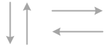 |
Flowlines | Arrows are used to connect the steps in a flowchart to show the flow or sequence of the problem-solving process |
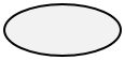 |
Terminal | An ellipse (or lozenge) is used to indicate the start and end of a flowchart. The Start is written in the ellipse, indicating the beginning of a flowchart. End, Stop, or Exit are written in the ellipse indicating the end of the flowchart. |
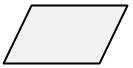 |
Input/Output | A parallelogram is used to read data (input) or to print data (output). |
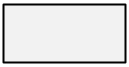 |
Process | A rectangle is used to represent the processing that occurs in the flowchart. |
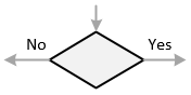 |
Decision | A diamond-shaped symbol is used to represent the decision-making step in a flowchart. A question is specified in the diamond. The next step in the sequence is based on the answer to the question, which is 「Yes」 or 「No」. |
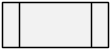 |
Subroutine | The predefined Process symbol represents the named process defined elsewhere. |
 |
On-page Connector | Pairs of on-page connectors are used to replace long lines on a flowchart page. |
 |
Off-page Connector | An off-page connector is used when the target is on another page. |
Flowlines
Flowlines
Shows relationships between different shapes.
Flowlines show the sequence of processes and use arrows to indicate the direction of each process. Each flowline usually connects two blocks.
Terminal
Terminal or

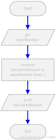
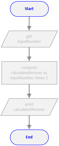
The terminator symbol marks the starting or ending point of the system. It usually contains the words "Start" or "End."
The terminal symbols, sometimes called start-stop symbols, show the Start and End points of the process.
Input/Output
Input / Output
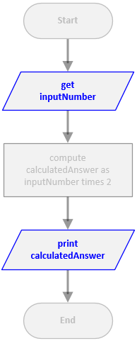
Represents material or information entering or leaving the system, such as a customer order (input) or a product (output).
Input/output symbols, represented by parallelograms, indicate input/output operations.
Process
Process
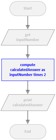
A box can represent a single step ("add two cups of flour") or an entire sub-process ("make bread") within a larger process.
Processing symbols, represented by rectangles, indicate processing steps, such as arithmetic statements. A process always has exactly one input and one output.
Decision
Decision
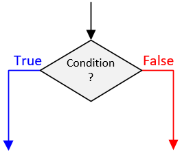
A decision or branching point. Lines representing different decisions emerge from different points of the diamond.
Decision symbols are represented by diamonds. The label in a decision block should be a question with only two possible answers. The decision block will have exactly one input and two outputs. The two outputs will be labeled with the two answers to the question to show the direction of the logic flow depending on the decision made.
Subroutine
Subroutine
Indicates a sequence of actions that perform a specific task embedded within a larger process. This sequence of actions could be described in more detail on a separate flowchart.
Subroutines are portions of code that run and return the execution point to the calling function. This allows you to write one subroutine and call it as often as you like from anywhere in the code. Subroutines make the code smaller and easier to test.
Connectors
The flowchart connector symbols are used to make a logic transfer to another location in the flowchart. A transfer location can be on the same page or another page. When you reach the bottom of the page or need to jump to another page, draw a flowchart connector symbol and connect it to the last item on the chart.
The connectors are used in pairs: in the originating and connected drawings. A flowline leaving a drawing requires a To connector. The same line in the second drawing requires a From connector. Both To and From connectors are represented by the same symbol, and both have the same connector number to identify the continuity.
On-Page Connector
Connects two or more parts of a flowchart that are on the same page.
On-page symbol: a circle with a number or letter to identify the matching transfer location. The on-page connector shows a jump from one point in the process flow to another. They are handy for avoiding flow lines that cross other shapes and flow lines. They are also handy for jumping to and from a sub-process defined in a separate area from the main flowchart.
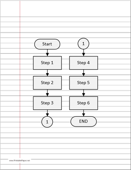
Figure 1.7: Sample Page Connector Example
Off-Page Connector
Connects two parts of a flowchart that are spread over different pages.
Off-page symbol: a square with a pointed bottom, containing a page number and a letter to identify the matching transfer location. The off-page connector shows the continuation of a process flowchart onto another page. The target page number must be added in the To symbol, and both To and From symbols have the same node letters (or numbers).
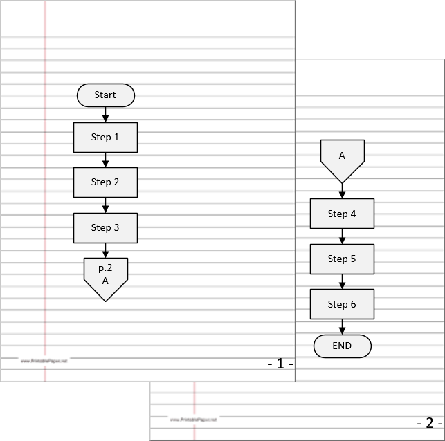
Figure 1.8: Off-Page Connector Example
Summary
- The flowchart can have only one start and one end symbol.
- On-page connectors are referenced using numbers.
- Off-page connectors are referenced using the alphabet.
- The general flow of processes is top to bottom or left to right.
- Arrows should not cross each other.
Further Reading
1.2 Flowchart Structures
Basic Structures
A structured flowchart is one in which all processes and decisions must fit into one of a few basic structured elements. The basic elements of a structured flowchart are shown below. It should be possible to take any structured flowchart and enclose all of the blocks within one of the following process structures. Note that each of the structures shown below has exactly one input and one output. Thus, the structure itself can be represented by a single process block.
Sequence Structure
The sequence structure is simply a series of processes carried out one after another. Most programs are represented at the highest level by a sequence, possibly with a loop from the end to the beginning.
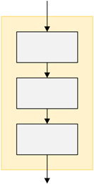
Figure 2.1: Sequence Structure
In a sequence structure, each block performs an action or task and then connects to the next in sequence. So, an action or event leads to the next ordered action in a predetermined order. A sequence can contain any number of tasks, but there is no chance to branch off and skip any tasks or actions. Once you start a sequence of actions, you must continue step by step to execute each action until the sequence ends. When run, the program must perform each action in order, with no possibility of skipping any action or branching to another.
Selection Structure
The selection structure is also known as an if-else structure and a decision structure. A selection structure is a programming feature that performs different processes based on whether a boolean condition is true or false. No matter which path is followed, continue with the next procedure.
There are two types of selection structures that can be used to achieve different outcomes.
if-else structure
The if-else structure is a two-alternative decision — actions are taken on both the true and the false sides.
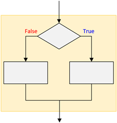
Figure 2.2.1: Selection Structure (if-else structure)
if structure
Sometimes, you may only want to perform an action or set of actions if a condition is true but do nothing special if it is false. This could be a flowchart as follows:
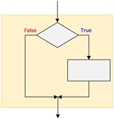
Figure 2.2.2: Selection Structure (if structure)
Case Structure
The case structure consists of a series of if-else statements that compare the same variable against different expression values.
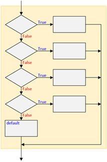
Figure 2.2.3: Nested if-else Structure
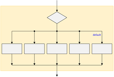
Figure 2.2.4: Case Structure
Loop Structures
Loop structures, also called repetition or iteration, repeat a set of actions based on the result. In other words, it can repeat the same actions over and over again until the condition is false.
There are two types of loop structures:
While-Loop Structure
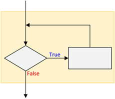
Figure 2.3: While Loop Structure
Do-While Loop Structure
The Do-While Loop structure differs from the While-Loop structure in that the action within the loop is always executed at least one time. This is equivalent to performing the actions once before going into a While-Loop. In the While-Loop structure, the actions may never be executed. Although the While-Loop structure is preferred, the Do-While Loop structure is sometimes more intuitive.
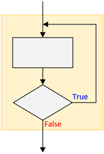
Figure 2.4: Do-While Loop Structure
Summary
- There are only three basic structures — sequence, selection, and loop structures.
- Each structure has one entry and one exit point.
- Structures attach to others only at entry or exit points.
1.3 Structured Program Design
Simple programming exercises can often be solved by just sitting down and writing code to implement the desired problem. Complex problems, however, can be difficult to write and impossible to debug if not implemented using a structured design process. Using a structured design process leads to the following benefits:
- Early detection of design flaws
- Programs that can be easily modified
- Clear and complete documentation
- Modular design to improve testing
- Modular design to break up a problem into smaller sections
The structured program mainly consists of three types of elements:
- Selection Statements
- Sequence Statements
- Iteration Statements
The program consists of well-defined, separate modules. The entry and exit in a Structured program are single-time events. It means that the program uses single-entry and single-exit elements. Therefore, a structured program is a well-maintained, neat, and clean program. This is why the Structured Programming Approach is well accepted in the programming world.
All logic problems can be solved using only these three structures — sequence, selection, and loop structures. A structured program includes only combinations of the three structures. All the structures can be combined in infinite ways and can be stacked or connected only at their entrance or exit points.
A structured program:
- Another structure can replace any individual action or step in a structure.
- Nesting: placing one structure within another
- Block: a group of structures that execute as a single unit
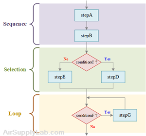
do stepA
do stepB
if conditionC is true then
do stepD
else
do stepE
endif
while conditionF is true
do stepG
endwhile
Figure 3.1: Structured Flowchart and Pseudocode
Flowchart Showing a Sequence Nested within a Selection
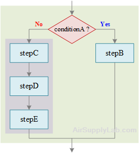
if conditionA is true then
do stepB
else
do stepC
do stepD
do stepE
endif
Selection in a Sequence within a Selection
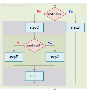
if conditionA is true then
do stepB
else
do stepC
if conditionF is true then
do stepG
else
do stepH
endif
do stepE
endif
Flowchart for For Loop within Selection within Sequence within Selection
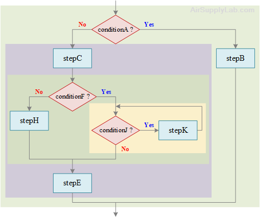
if conditionA is true then
do stepB
else
do stepC
if conditionF is true then
while conditionJ is true
do stepK
endwhile
else
do stepH
endif
do stepE
endif
1.4 Unstructured Program
Examples of Good and Bad Structured Programs
The following figure shows examples of properly and improperly structured flowcharts. The unstructured flowchart is an example of what can happen when a program is written first and then a flowchart is created to represent it. This type of unstructured flow is often called 'spaghetti' programming and normally has elements of its structure impossibly intertwined around other elements. A program of this sort is complicated to understand, implement, debug, and maintain.
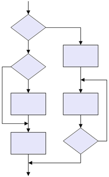
Figure 4.1: Structured Flowchart Example
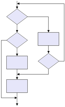
Figure 4.2: Unstructured Flowchart Example
Flowchart of Number-Double Problem
You are designing a program to ask users to enter an integer number. If the input number is 0, stop the program; otherwise, calculate the doubled value and display it on the screen. Then repeat the procedure again.
According to the question, you may draw the flowchart as below. Then, you have to think: Is this flowchart structured?
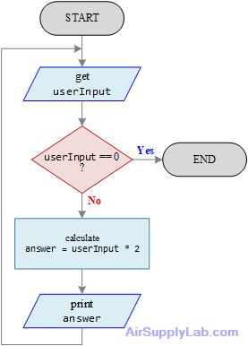
Figure 4.3: Unstructured Flowchart of a Number-Doubling Problem
The flowchart in Figure 4.3 may not be easy to tell it is structured or not. Reorganize the flowchart as shown below, and you will find that it does not look exactly like any of the basic structured flowcharts discussed in 1.2 Flowchart Structures.
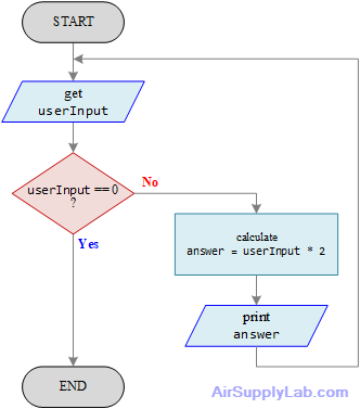
Figure 4.4: Functional but Nonstructured Flowchart
For the loop in Figure 4.4 to be a structured loop, the logic must return to the decision when the sequence ends. The flowchart in Figure 4.5 shows the flow of logic returning to the decision immediately after the sequence. Now the flowchart is structured.
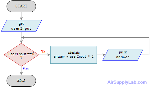
Figure 4.5: Structured, But Nonfunctional, Flowchart of Number-Doubling Problem
Let us follow the flowchart in Figure 4.5 to run the program. Assuming that when the program starts, the user enters 10 for the value of userInput. Ten is not equal to zero, so the number is doubled, and 20 is printed out on the screen. Then the question userInput equal to zero is asked again. It cannot be false because the logic did not reach the get userInput block; the value of userInput never changed. Therefore, 10 is doubled again, and the answer 20 prints again. This goes on forever, with 20 being printed repeatedly. The program logic shown in the above diagram is structured, but it does not work.
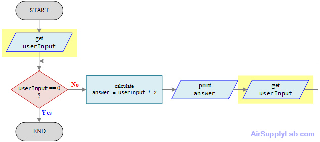
How can the number-doubling problem be structured and still work? Sometimes, some extra steps may be added to the flowchart to make the program structured. In this case, after printing the answer on the screen and before checking the userInput value, the get userInput step must be added to update the userInput value.
start
get userInput
while userInput is not equal to zero
calculate answer = userInput * 2
print answer
get userInput
endwhile
end
Figure 4.6: Functional, Structured Flowchart for the Number-Doubling Problem
Unstructured Selection
You are designing a system to determine customer discounts based on age. If they are younger than 10 or older than 55, they can get a 15% discount; otherwise, they can get a 10% discount.
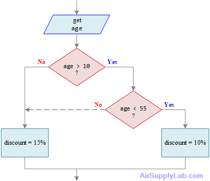
Figure 4.7: Unstructured Selection
Is the flowchart segment in Figure 4.7 structured?
No, it is not constructed from the three basic structures. There are two flowlines pointing to the same processing block (discount = 15%) from different selection structures that must be untangled.
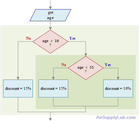
Follow the line on the left side of the Question (age < 55), and untangle it by repeating the step that is tangled. The result is the flowchart shown in Figure 4.8. The entire flowchart is structured — it has a sequence followed by a selection inside a selection.
get age
if age is greater than 10 then
if age is less than 55 then
discount = 0.1
else
discount = 0.15
endif
else
discount = 0.15
endif
Figure 4.8: Finished Flowchart
Unstructured Loop
The flowchart in Figure 4.9 is neither a while loop (which begins with a decision and, after an action, returns to the decision) nor a do-while loop (which begins with an action and ends with a decision that might repeat the action). Instead, it begins like a while loop, with a process followed by a decision, but one branch of the decision does not repeat the initial process; instead, it performs an additional new action before repeating the initial process.
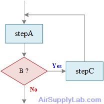
Figure 4.9: Unstructured Loop
Figure 4.10 shows the same logic as Figure 4.9, but now it is structured, with a sequence of two actions within the loop. Does this diagram look familiar to you? It uses the same technique of repeating a needed step as in [Flowchart of Number-Double Problem]
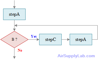
Figure 4.10: Sequence and Structured Loop That Accomplishes the Same Tasks as Figure 4.9
1.5 Flowchart on the Design of Algorithms
Basically, the design of an algorithm must satisfy the following criteria:
- Input data: Clearly indicate which data to enter in the program and how to enter it.
- Output result: At least one output result is produced.
- Clarity: The procedure described must be clearly feasible.
- Finiteness: The work must be done within a limited number of steps.
- Validity: Each step can be expressed with valid instructions.
Generally speaking, the algorithm of any problem is nothing more than three steps: (1) input data, (2) process data, (3) output results.
Steps to Design a Flowchart Diagram
- The first step is to express the algorithm steps in natural language;
- The second step is to determine the logical structure contained in each algorithm step and represent it with the corresponding block diagram to obtain the block diagram of the step;
- The third step is to connect the block diagrams of all steps with flow lines and add terminal boxes to form a block diagram representing the entire algorithm.
1.6 Psedocode
Introduction: What Is Pseudocode
Pseudocode is a way of describing an algorithm that sits between human language and a real programming language. It uses English-like keywords (such as IF, WHILE, PRINT) to express a program's logic, without being bound to the syntax of any particular language. In short, it lets you focus on what the program should do, rather than how to write it in a specific language.
1. The Role of Pseudocode in Program & System Analysis
1.1 Focus on logic, set syntax aside
During analysis and design, the priority is to get the solution steps right. Pseudocode lets the designer establish the algorithm first; once the logic is settled, it can be translated into C, C++, Python, or any other language. This greatly reduces the burden of fighting syntax and reasoning about logic at the same time.
1.2 A common language for communication and documentation
Almost anyone can read pseudocode, which makes it ideal for discussing designs in a team, doing code reviews, or serving as part of project documentation. Because it is language-independent, a C engineer and a Python engineer can communicate through the same pseudocode.
1.3 A blueprint for writing code
Writing pseudocode first, then translating it line by line into real code, reduces structural errors during implementation. It also makes it easy to inspect the logic for gaps (such as boundary conditions or loop-termination conditions) before any real coding begins.
1.4 A bridge for teaching and learning
For beginners, pseudocode removes syntactic details so learners can first master computational thinking and algorithmic structure, making the transition to any language smoother afterward.
2. Pseudocode vs. Flowchart
Both are tools for describing algorithms, but they differ in form and in where they fit best:
| Aspect | Pseudocode | Flowchart |
|---|---|---|
| Form of expression | Text (English-like statements) | Graphics (boxes, arrows, decision diamonds) |
| Closeness to code | High; can be translated almost line by line | Low; must be converted into code structures |
| Readability of complex logic | Good; nested loops / multiple conditions stay clear | Can become large and tangled with crossing arrows |
| Visual intuitiveness | Requires reading text to follow the flow | Excellent; flow and branches seen at a glance |
| Cost to create and edit | Low; plain text, edited on the spot | High; needs a drawing tool, slower to adjust |
| Version control/diff | Good; plain text diffs directly | Poor; image files are hard to compare |
| Best audience | Engineers, programmers | Non-technical readers, process overviews |
Summary: A flowchart wins at showing the overall flow at a glance, making it ideal for explaining to non-technical people or presenting a system overview. Pseudocode excels at being close to code, being easy to maintain, and expressing complex logic, making it ideal for actual design and implementation. In practice, the two are often combined — use a flowchart to capture the big picture, then pseudocode to refine the algorithm inside each block.
3. Pseudocode Keywords: Categories and Usage
Pseudocode keywords (action verbs) are conventionally written in UPPERCASE to distinguish them from variables and conditions. The following lists common keywords by function, with examples.
3.1 Structure
Keywords: ALGORITHM, BEGIN / START, END / STOP
Mark the start and end of the algorithm and delimit the whole program block.
ALGORITHM Greeting
BEGIN
    PRINT "Hello, World"
END
3.2 Control Flow
Keywords: IF, THEN, ELSE, ELSEIF, ENDIF, SWITCH, CASE, OTHERWISE, DEFAULT, ENDSWITCH, OF
Decide which block of code runs based on a condition; handle branching.
IF score >= 60 THEN
    DISPLAY "Pass"
ELSEIF score >= 40 THEN
    DISPLAY "Retake"
ELSE
    DISPLAY "Fail"
ENDIF

SWITCH grade OF
    CASE "A": DISPLAY "Excellent"
    CASE "B": DISPLAY "Good"
    OTHERWISE: DISPLAY "Keep trying"
ENDSWITCH
3.3 Loops
Keywords: FOR, FOREACH, EACH, IN, TO, DOWNTO, STEP, DO, ENDFOR, WHILE, ENDWHILE, REPEAT, UNTIL, LOOP, BREAK, CONTINUE
Repeat a block of code. FOR is for a known number of iterations, WHILE runs while a condition holds, and REPEAT...UNTIL runs at least once.
FOR i <- 1 TO 10 STEP 1 DO
    PRINT i
ENDFOR

WHILE count <= 100 DO
    SET count <- count + 1
ENDWHILE

REPEAT
    READ n
UNTIL n = 0
3.4 Subprograms
Keywords: FUNCTION, ENDFUNCTION, PROCEDURE, ENDPROCEDURE, METHOD, CALL, RETURN
Encapsulate logic into reusable units. A FUNCTION usually returns a value; a PROCEDURE emphasizes performing an action.
FUNCTION Max(a, b)
    IF a > b THEN
        RETURN a
    ELSE
        RETURN b
    ENDIF
ENDFUNCTION

CALL Max(3, 7)
3.5 Declaration & Assignment
Keywords: DECLARE, DEFINE, SET, INIT, CONST
Declare variables, set initial values, or define constants. Assignment is commonly written as <- or :=.
DECLARE total AS INTEGER
SET total <- 0
INIT counter <- 1
CONST PI <- 3.14159
3.6 Input
Keywords: INPUT, READ, GET, OBTAIN
Obtain data from a user, a file, or a sensor.
INPUT name
READ value
GET temperature
OBTAIN userChoice
3.7 Output
Keywords: OUTPUT, PRINT, DISPLAY / SHOW, WRITE / PUT
Display results, send messages, or write data.
PRINT "Result ="
DISPLAY average
WRITE record
OUTPUT total
3.8 Processing & Math
Keywords: COMPUTE / CALCULATE, DETERMINE, INCREMENT / BUMP, DECREMENT
Perform calculations, change variables, or manipulate data.
COMPUTE area <- width * height
CALCULATE average <- sum / n
INCREMENT counter
DECREMENT lives
3.9 Operators & Boolean
Operators: assignment <- :=; comparison = <> (or ≠) < > <= >=; arithmetic + - * / MOD DIV; logical AND OR NOT. Boolean values: TRUE, FALSE.
SET flag <- TRUE
IF (a > 0) AND (b <> 0) THEN
    SET remainder <- 17 MOD 5
ENDIF
3.10 Error Handling
Keywords: TRY, CATCH, THROW, NULL
TRY
    OBTAIN data
CATCH error
    DISPLAY "Something went wrong"
Comments
A comment begins with // or #. Note: a // or # that appears inside a string ("…" or '…') is not a comment — a URL, for example, will not be misread.
SET url <- "http://example.com"   // this is the comment; the // in the string is not
INPUT age   # read the age
4. Worked Example
The following algorithm, which computes the average of N numbers, brings together keywords from each category:
ALGORITHM ComputeAverage
BEGIN
    INPUT n                         // how many numbers
    SET sum <- 0

    FOR i <- 1 TO n STEP 1 DO
        INPUT value
        COMPUTE sum <- sum + value
    ENDFOR

    IF n > 0 THEN
        COMPUTE average <- sum / n
        DISPLAY "Average =", average
    ELSE
        DISPLAY "No data"
    ENDIF
END
How to use: In a Joomla article, place your code inside the following structure to have it highlighted automatically (as done for every example in this article):
<pre class="line-numbers language-pseudocode"><code> ...your pseudocode... </code></pre>Flowchart Examples
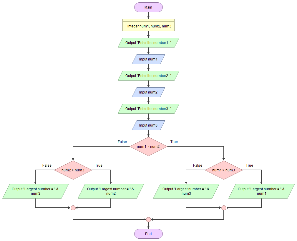
Find Largest of Three Given Numbers
Ask the user to enter three integers and find the largest of them. Given three numbers num1, num2, and num3. The task is to find the largest of the three numbers.
Enter the number1 = 12
Enter the number2 = 62
Enter the number3 = 27
Largest number = 62
Algorithm
To find the greatest number of three given numbers:
- Ask the user to enter three integer values.
- Read the three integer values into num1, num2, and num3 (integer variables).
- Check if num1 is greater than num2.
- If true, then check if num1 is greater than num3.
- If true, then print 'num1' as the greatest number.
- If false, then print 'num3' as the greatest number.
- If false, then check if num2 is greater than num3.
- If true, then print 'num2' as the greatest number.
- If false, then print 'num3' as the greatest number.
Leap year
A common year has 365 days, and a leap year has 366 days; the extra day is the 29th of February.
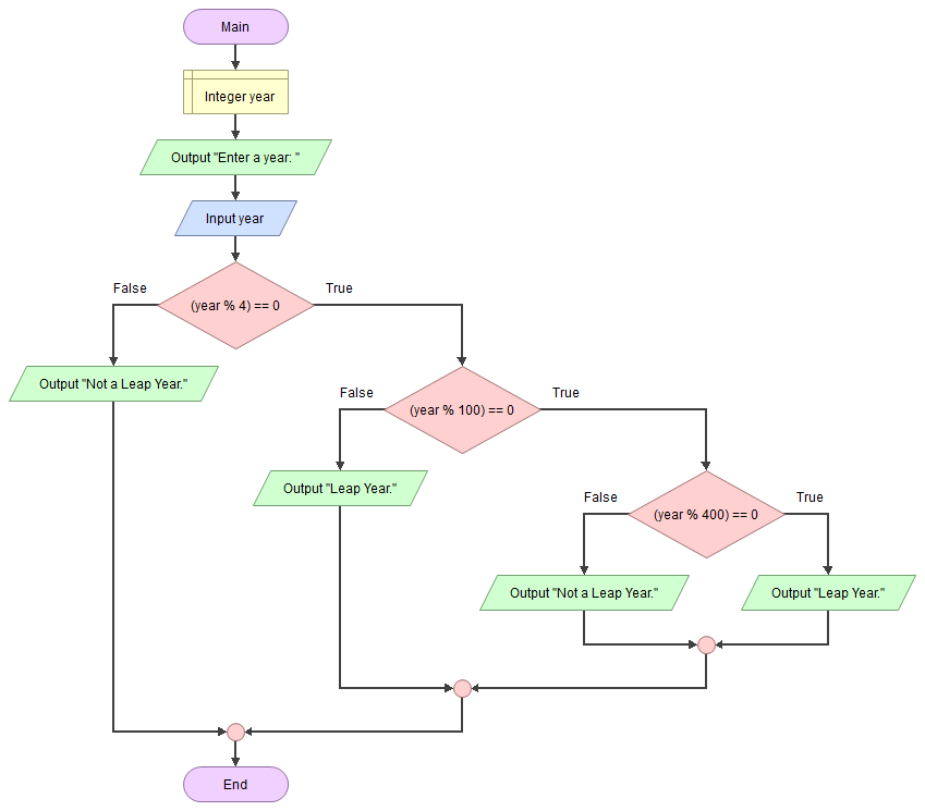
Leap Year Algorithm 1
Leap Year Algorithm 1
The algorithm to determine if a year is a leap year is as follows:
- Leap years are years that are exactly divisible by 4.
- Except if it is exactly divisible by 100, then it is not a leap year.
- Except if it is exactly divisible by 400, then it is a leap year.
Design a flowchart that takes a year as input and determines whether it is a leap year.
Leap Year Algorithm 2
Leap Year Algorithm 2
The algorithm to determine if a year is a leap year is as follows:
- A year is called a leap year if it is divisible by 400.
- If a year is not divisible by 400 as well as 100, but it is divisible by 4 then that year is also a leap year.
Design a flowchart that takes a year as input and determines whether it is a leap year.
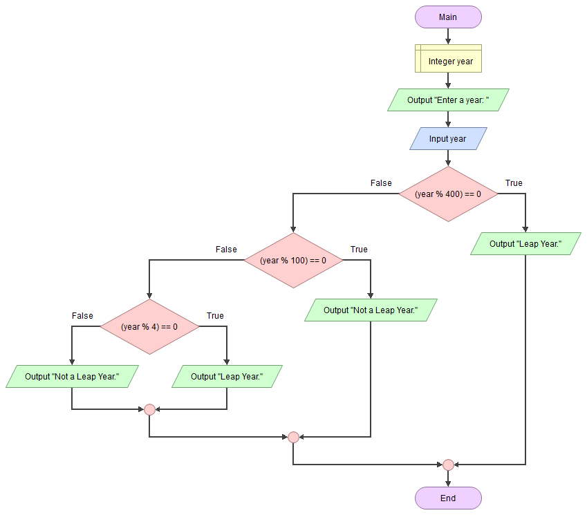
Question:
- Use the flowchart to determine whether the following year is a leap year.
- 2000
- 2004
- 2101
- 2100
- 1986
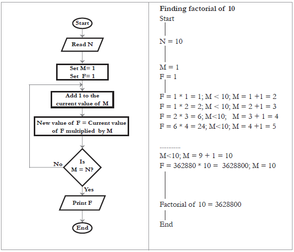
Find Factorial of Number
Factorial is used in many areas of mathematics, but mainly in permutations and combinations. Factorial is the product of all positive numbers from 1 to n (the user-entered number). Simply, we can say that the factorial of n is $1 \times 2 \times 3 \times \cdots \times n$.
Note: No factorial exists for negative numbers, and the value of 0! is 1.
Algorithm
The factorial of a positive number is:
$n! = 1 \times 2 \times 3 \times \cdots \times n$
For example:
$5! = 5 \times 4 \times 3 \times 2 \times 1 = 120$
| n | n! |
|---|---|
| 0 | 1 |
| 1 | 1 |
| 2 | 2 |
| 3 | 6 |
| 4 | 24 |
| 5 | 120 |
| 6 | 720 |
| 7 | 5040 |
| 8 | 40320 |
| 9 | 362880 |
| 10 | 3628800 |
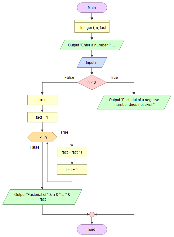
Homework
Q01 Draw Flowcharts
Use an online flowchart website to draw the following flowcharts, export them as a PDF file then submit them before the due. (Do not hand-draw any flowcharts.)
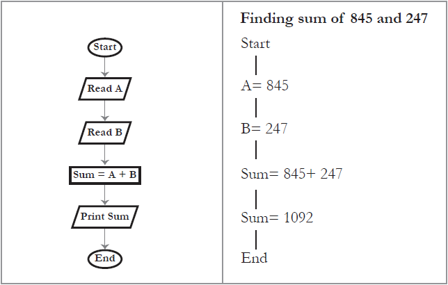
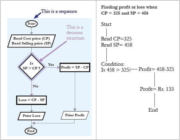
* Draw the flowchart on the left, including comments and arrows.
- Find the sum of two numbers.
- Find profit or less
- Find factorial of a given number N ($N! = 1 \times 2 \times 3 \times \cdots \times N$)
Q02:Match the elements of a flowchart
Match the elements of a flowchart and their purpose of use in the following:
The elements include: [Loop], [Start], [Process], Input], [Stop], [Decision], and [Output]
| Purpose | Use |
|---|---|
| Calculate the total of A, B, and C. | |
| Indicate that the problem has been solved. | |
| Find if a number is greater than the other. | |
| Read a number and calculate its factorial. | |
| Read three numbers. | |
| Print the total. | |
| Indicate the beginning of a problem-solving flow. |
Q03: Puzzle
Complete the crossword puzzle.
| 1 | |||||||||
| 2 | |||||||||
| 3 | |||||||||
| 4 | |||||||||
| 5 | |||||||||
Across
- I am a rectangle in a flowchart. What do I represent?
- When you want to show a decision-making step, you can use this box.
- You can use me to communicate ideas and graphically represent a problem-solving process.
- I connect two geometrical boxes in a flowchart.
Down
- In the flowchart, I represent available data or information.
- All flowcharts begin with me. I am elliptical in shape.
Q04: Programming Structure
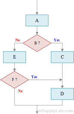
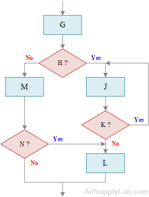
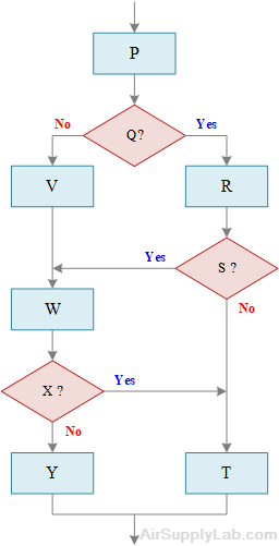
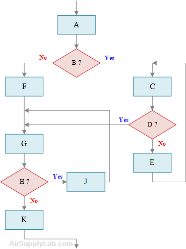
For each of the unstructured flowcharts below, redraw them in such a way that the logic remains the same but is structured. Also, highlight the different types of structures. Do not hand-draw any flowcharts.