Lab 13: The Response of an RC Circuit
Objective
- Validate the R-C response for a partially and fully charging/discharging capacitor.
- Check the validity of Kirchhoff’s Voltage Law for an R-C circuit.
Equipments
Background
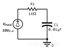
Consider the Thévenin RC circuit with the square wave voltage input. The time dependent voltage across the capacitor is:
$\begin{array}{l} {v_C}(t) = {V_{OC}} + \left( {{v_c}({0^ - }) - {V_{OC}}} \right) \times {e^{ - t/\tau }} \equiv {V_{final}} + ({V_{initial}} - {V_{final}}) \times {e^{ - t/\tau }}\\ \end{array}$
What determines whether a capacitor is partially or completely charged is the pulse width (pw) of the square wave input. Two cases will be considered:
- pw = 5τ and
- pw = 2.
For a pulse width of 5τ or greater, the capacitor will have enough time to completely charge up and completely discharge.
For a pulse width of 2τ, the capacitor will not have had enough time to completely charge up or completely discharge. It will require 5 cycles of the constant square wave input to reach its final steady state value. The repeated application of the complete response for a constant input for these 5 cycles will ultimately achieve the final steady-state value that is observed experimentally on the oscilloscope.
Procedure
Exp #1: Setting up the Function Generator
- Set the function generator to the square-wave mode and set the frequency to 10 kHz.
- Adjust the amplitude until a 10 VPP signal is obtained. Adjust the function generator’s OFFSET to 5-Volts to offset the negative pulse. Then adjust the zero reference line at the bottom of the screen to increase the accuracy for measuring voltages
- Now adjust the sweep control until two full periods appear on the screen. Using the scope display, adjust the frequency of the function generator to ensure that the output frequency is exactly 10 KHz. (Hint: determine how many horizontal divisions should encompass a 10 KHz signal, and make the necessary adjustments.)
- How is the pulse width pw and period T of the square wave voltage related to the frequency f for the cycle?
Exp #2: R-C Response for a pulse width of 5
Construct the following circuit:

Part 2A: Measurements for a pulse width of 5τ
- Determine the time constant τ of the circuit using the actual resistor and capacitor values that will be used in the experiment.
- From the time constant , determine the period T = 10τ required for a capacitor to fully charge and discharge. Using the period, determine the frequency for the voltage source.
- Adjust the function generator in order to see the charging and discharging of the capacitor (that is, at least 10).
- Predict the capacitor’s and resistor’s voltage (vC-thy(t) & vR-thy(t)) for the charging phase for time constants (τ, 3τ, 5τ) and for the discharging phase for time constants (6τ, 8τ, 10τ) Hint: an excel spread sheet calculations will reduce the redundancy; however, a sample calculation is still required.
- Measure the capacitor’s voltage vC-expt(t) for the charging and discharging phases. Make sure that the capacitor is connected to the ground and make the necessary adjustments to ensure that the total waveform is on the screen.
- Switch the positions of the resistor and capacitor. Measure the resistor’s voltage
vR-expt(t) for the charging and discharging phases. Accurately plot vC-expt(t) and
vR-expt(t) on the same graph paper. - Compare the predicted and measured values for the capacitor’s and resistor’s voltages during the charging and discharging phases. How do they compare?
- Use KVL to make sure that the voltage source value equals the sum of the resistor and capacitor voltages (vS = vR + vC) at time t = 3τ. Make this comparison graphically as well as numerically. Does KVL hold for RC circuits? Explain.
Part 2B: PSpice Simulation
Simulate the RC circuit using the determined time constant.
Exp #3: R-C Response for a pulse width of 2τ
Part 3A: Measurements for a pulse width of 2τ
- From the time constant, determine the period T, the pulse width T/2, and the frequency f of the applied square wave.
- Adjust the function generator in order to see the charging and discharging of the capacitor. Is the capacitor full charging and discharging? Explain your reasoning.
- Predict and measure the capacitor’s and resistor’s voltages (in steady-state) using the same process as in part (2A). For the charging phase use the times (τ and 2τ) and for the discharging phase (3τ and 4τ).
- Compare the predicted and measured values for the capacitor’s and resistor’s voltage during the charging and discharging phases. How do they compare?
- Use KVL to make sure that the voltage source value equals the sum of the resistor and capacitor voltages (vS = vR + vC) at time t = τ. Make this comparison graphically as well as numerically. Does KVL hold for RC circuits? Explain.
Part 3B: PSpice Simulation for a pulse width of 2τ
Simulate the RC circuit using the determined time constant.
Part 1: Setting up the Function Generator