Lesson 18: Timer - Input Capture (Input Edge-Time) Mode
In Input Capture (or Edge-Time) mode, the timer is configured as a 24-bit or 48-bit up- or down-counter including the optional Prescaler with the upper timer value stored in the GPTMTnPR register and the lower bits in the GPTMTnILR register. Table 1 shows that when the timer is enabled in Input Capture mode, what initial value will be loaded into the Timer counter registers.
Table 1: Counter Values When the Timer is Enabled in Input Event-Count Mode
| Register | Count-Down Mode | Count-Up Mode | Description for the Register |
| TAR TBR |
GPTMTAILR GPTMTBILR |
0x0 | The counter value at which the last edge event took place |
| TAV TBV |
GPTMTAILR GPTMTBILR |
0x0 | The current value of the Timer |
| TAPS TBPS |
GPTMTAPR GPTMTBPR |
0x0 | 16/32-bit GPTM: The current value of the Timer Prescaler for periodic snapshot mode 32/64-bit Wide GPTM: The current value of the Timer Prescaler in the 32-bit modes |
| TAPV TBPV |
GPTMTAPR GPTMTBPR |
0x0 | 16/32-bit GPTM: Not used in this mode 32/64-bit Wide GPTM: this register shows the current value of the Timer Prescaler in 32-bit modes |
In this mode, the timer is capable of capturing three types of events: rising edge, falling edge, or both edges. The input signal must be High (or Low) for at least two system clock periods following the rising (or falling) edge. Based on this criteria, the maximum input frequency for edge detection is 1/4 of the system clock frequency. Table 1 shows the values that are loaded into the timer register when the timer is enabled in different counting modes.
The timer counter is a free-running counter and never stop once the timer is enabled. Before we start the edge detection, the "Capture Event" flag in the Raw Interrupt Status register (GPTMRIS) need to be cleared using the Interrupt Clear Register (GPTMICR). When the selected edge is detected, the current timer counter value will be stored into the GPTMTnR register, (GPTMTnPV value to GPTMTnPS register in 32/64-bit Timer), and a "Capture Event" flag in the Raw Interrupt Status register (GPTMRIS) will be triggered to 1.
16-bit Timer Input Capture Mode with an 8-bit Prescaler
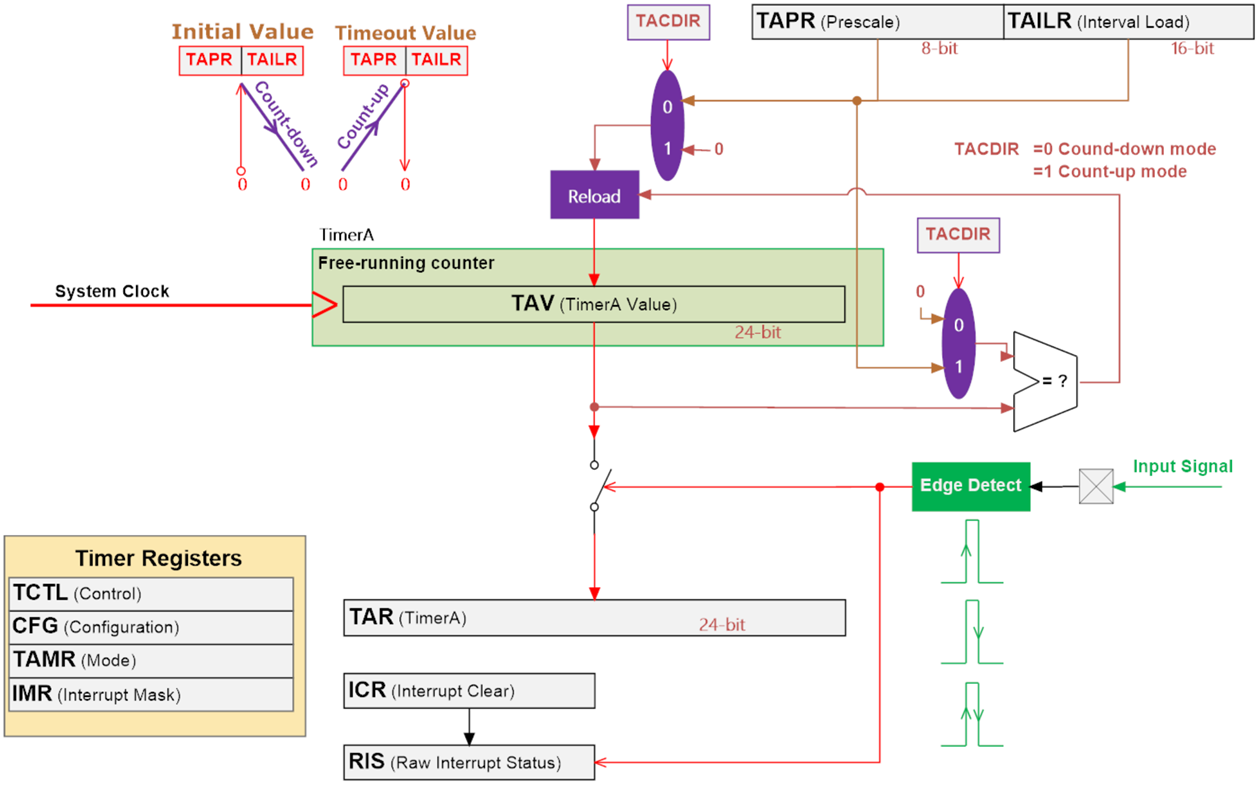
Figure 1: GPTM Module Input Capture Block Diagram
32-bit Timer Input Capture Mode with an 16-bit Prescaler
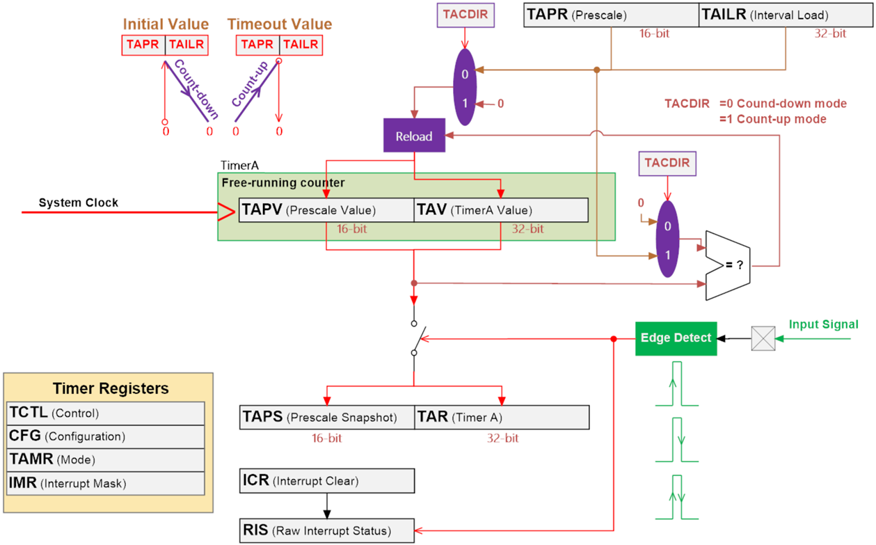
Figure 2: GPTM Module Input Capture Block Diagram
Applications of Input Capture Function
For the 16-bit timer input capture, the longest period of the signal that can be measured with the Prescaler configuration to GPTMTnPR register set to 0xFF (255) is:
Assume the system clock is 80 MHz: \(\frac{{{2^{24}}}}{{80MHz}} = 209.7152ms\)
This means that the period of an unknown signal must be shorter than 209.7 ms with 80 MHz of the system clock.
Period Measurement
Configure the timer module to trigger the capture on either a rising edge or a falling edge. Then wait for the event, or enable an interrupt for the event. In either case, when the event occurs, the value of the timer count will be latched in the capture register (TAR/TBR). Read the value and save it. Then wait for the second capture event.
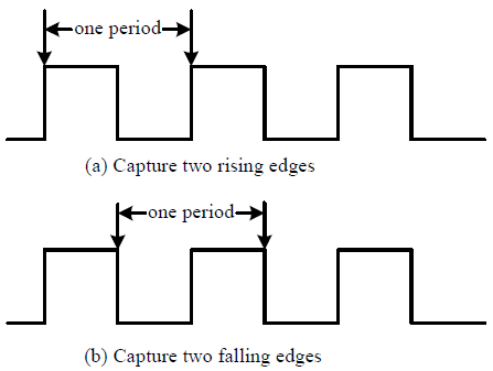
Period of a signal = time difference between two captures.
Pulse-Width Measurement
Pulse-width measurement operates in much the same way except for the capture on both edges. To measure pulse-width, configure the timer module to trigger the capture on a rising edge. Then wait for the event, or enable an interrupt for the event. In either case, when the event occurs, the value of the timer count will be latched in the capture register (TAR/TBR). Read the value and save it. Then immediately reconfigure the time module to capture on the falling edge. When the falling edge event occurs, then read the value on the capture register and save it. Now subtract the two saved reading values and that gives the pulse width in counts.

A pulse width of a signal = time difference between rising and falling edge
Continuous Signals
On-shot Signals
Frequency Measurement
Duty Cycle Measurement
Timer Rolls Over
Use two unsigned ints (32-bit) variables to store two capture values and then calculate the period measurement. The period measurement in the counter unit is equal to the first capture count value subtracted with the second capture counter value.
\(Perio{d_{Count}} = (FirstCapturedValue) - ({{\rm Sec}\nolimits} ondCapturedValue)\)
Theoretically speaking, the first capture counter value should be great than the second capture counter value when the timer is working on the count-down mode. However, when the timer rolls over, the timer will reload the counter value from the LOAD value and continue counting to zero. Therefore, the second capture counter value may have changed to great than the first capture counter value. Consider the case, when the first captured timer value is 0x0096 (or decimal value of 150), and the second captured timer value is 0xFE3E (or decimal value of 65086). The result of 0x96 - 0xFE3E is 0xFFFF0258.