Lesson 15: Universal Asynchronous Receiver Transmitter (UART)
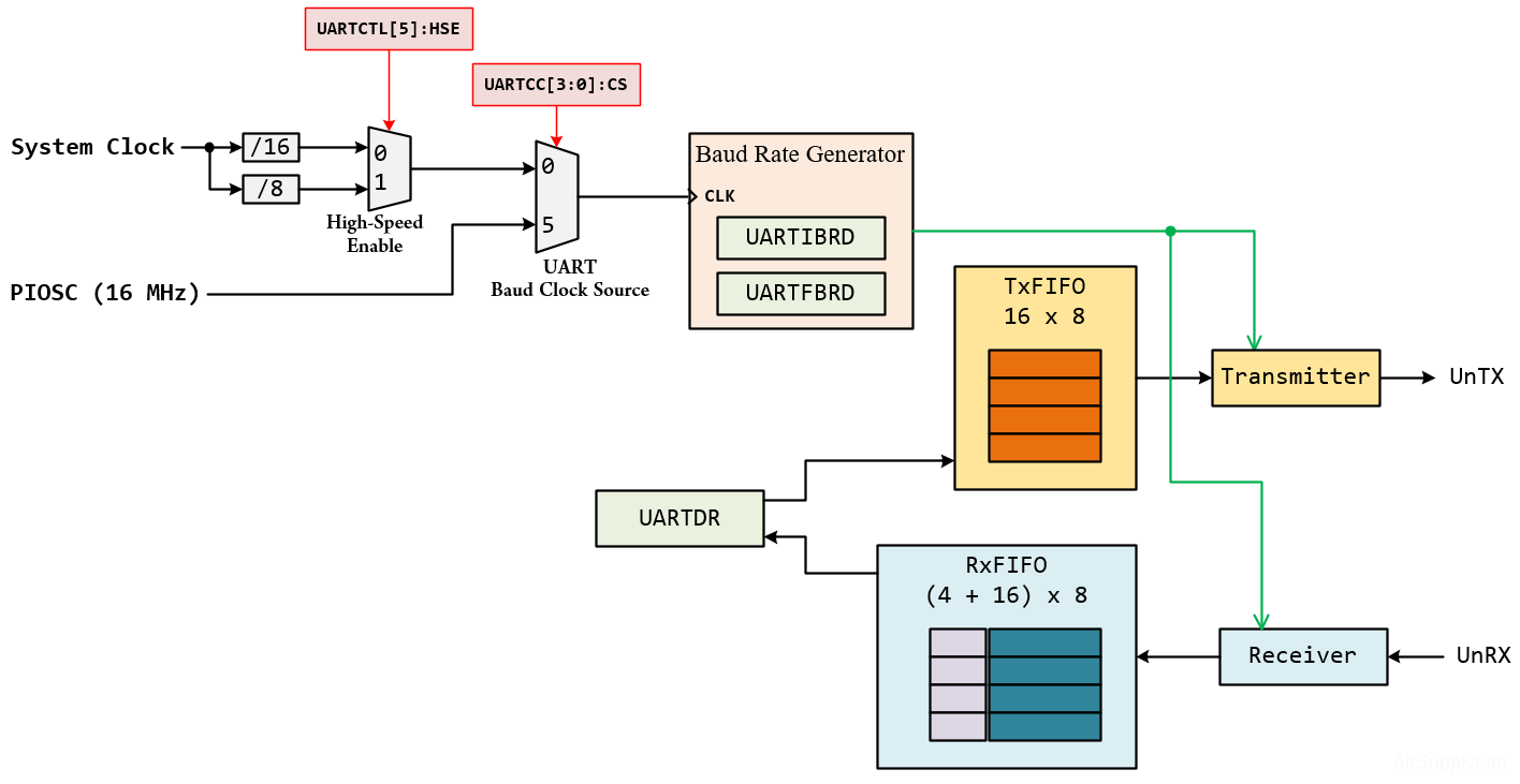
The TM4C123GH6PM and TM4C1294NCPDT controllers include eight UART ports (UART0 ~ UART7). Each of these ports features separate 16-by-8 transmit and receive FIFOs, a programmable baud rate generator, automatic generation and removal of the start, stop, and parity bits, line break generation, and detection, a choice of five to eight data bits, multiple parity types, and one or two stop bits, modem and flow control.
The UART is configured for transmitting and/or receiving via the TXE and RXE bits of the UART Control (UARTCTL) register. Before any control registers are programmed, the UART must be disabled by clearing the UARTEN bit in UARTCTL.
Baud Rate Generation
The baud rate affects how fast the data can be sent. Baud rate is basically the frequency of the TX or RX pulses. The baud rate can be evaluated by the following formula:
\(BaudRate = \frac{{{f_{UARTClk}}}}{{BRD}}\)
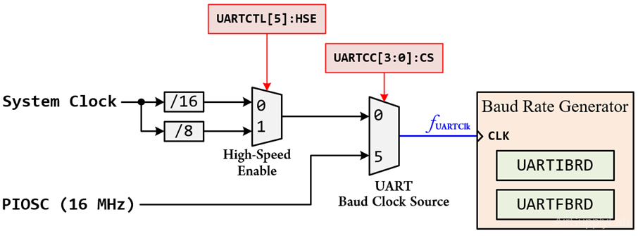
The UART clock source can be configured from the main system clock, the internal precision oscillator (PIOSC), or other clock selections.
EK-TM4C123GXL LaunchPad - Circuit
The UART clock source for TM4C123G:
| UARTCC[3:0] CS |
UARTCTL[5] HSE |
UART Clock Source |
| 0 | 0 | \({f_{UARTClk}} = \frac{{{f_{SysClk}}}}{{16}}\) |
| 0 | 1 | \({f_{UARTClk}} = \frac{{{f_{SysClk}}}}{8}\) |
| 5 | X | \({f_{UARTClk}} = PIOSC = 16MHz\) |
EK-TM4C1294XL LaunchPad - Circuit
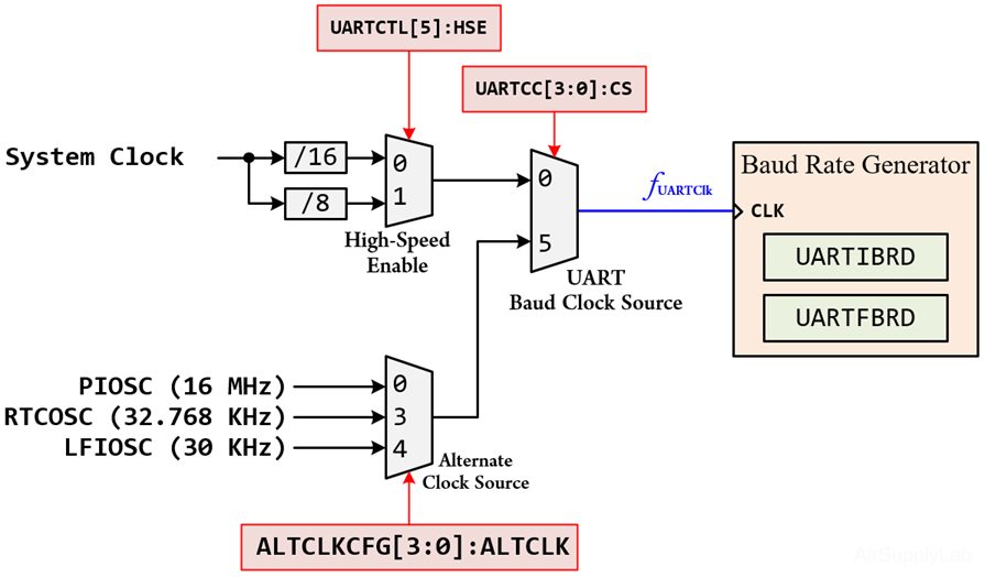
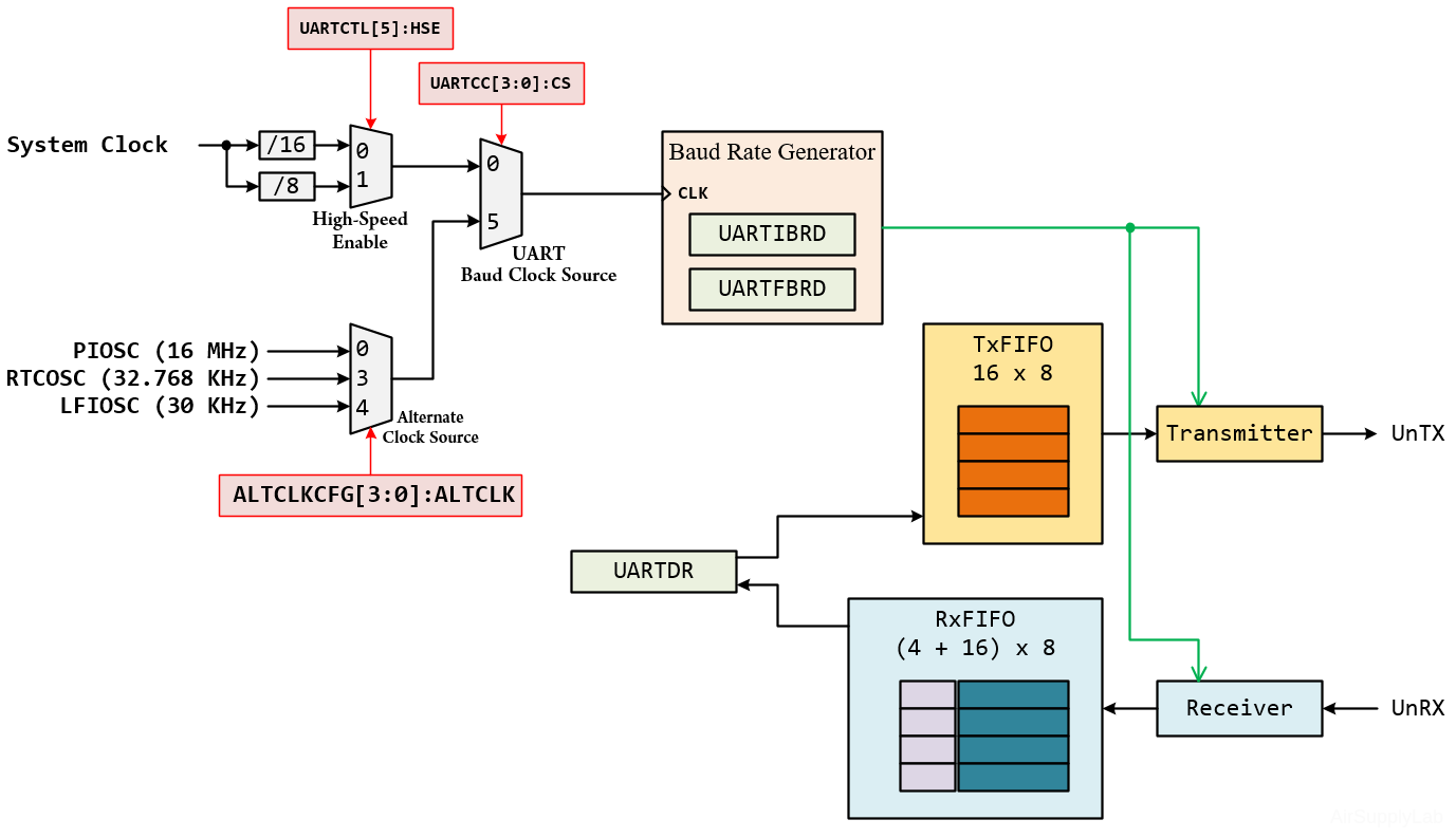
UART clock source for TM4C1294:
| UARTCC[3:0] CS |
UARTCTL[5] HSE |
ALTCLKCFG[3:0] ALTCLK |
UART Clock Source |
| 0 | 0 | X | \({f_{UARTClk}} = \frac{{{f_{SysClk}}}}{{16}}\) |
| 0 | 1 | X | \({f_{UARTClk}} = \frac{{{f_{SysClk}}}}{8}\) |
| 5 | X | 0 | \({f_{UARTClk}} = PIOSC = 16MHz\) |
| 5 | X | 3 | \({f_{UARTClk}} = RTCOSC = 32.768KHz\) |
| 5 | X | 4 | \({f_{UARTClk}} = LFIOSC = 30KHz\) |
The baud rate generator allows speeds up to 5Mbps for regular speed (system clock divided by 16), or 10Mbps for high speed (system clock divided by 8)
The baud-rate divisor (BRD) is a 22-bit number consisting of a 16-bit integer and a 6-bit fractional part. The 16-bit integer is loaded through the UART Integer Baud-Rate Divisor (UARTIBRD) register and the 6-bit fractional part is loaded with the UART Fractional Baud-Rate Divisor (UARTFBRD) register. The baud-rate divisor has the following relationship to the UART:
\(BRD = \frac{{{f_{UARTClk}}}}{{BaudRate}} = BR{D_{Integer}} + BR{D_{Fraction}}\)
By default, the UART clock source is connected to Low-Speed mode (System Clock / 16). Therefore, the calculation of the baud rate divisor will be translated as follows:
\(BRD = \frac{{{f_{UARTClk}}}}{{BaudRate}} = \frac{{{f_{SysClk}}}}{{16 \times BaudRate}} = BR{D_{Integer}} + BR{D_{Fraction}}\)
The UARTIBRD is the integer part of the BRD.
\(UARTIBRD = BR{D_{Integer}}\quad < = 65,535\)
The UARTFBRD can be calculated by taking the fractional part of the BRD, multiplying it by 64, and adding 0.5 to account for rounding errors.
\(UARTFBRD = Integer(BR{D_{Fraction}} \times 64 + 0.5)\)
For example, assume system clock frequency = 8 MHz, and the baud rate which we want the UART to be running at is 19200 bps. Therefore, the value of divisor is:
\(BRD = \frac{{{f_{SysClk}}}}{{16 \times BaudRate}} = \frac{{8MHz}}{{16 \times 19200}} = 26.04167\)
- Take 26 as the integer part and let it be BRDInteger. So, we have BRDInteger = 26.
- Take 0.04167 as the decimal part and let it be BRDFraction. So, we have BRDFraction = integer( 0.04167 * 64+ 0.5 ) = 3
- Save BRDInteger (= 26) to UARTIBRD register, and BRDFraction (= 3) to UARTFBRD register.
Initialization and Configuration
To use the UART, the peripheral clock must be enabled by setting the appropriate bit in the RCGCUART register. In addition, the clock to the appropriate GPIO module must be enabled via the RCGCGPIO register in the System Control module.
Before to use UART peripheral, the following information must be decided and calculated:
- Define the UART configuration for both devices:
- Baud rate: 1200, 2400, 4800, 9600, 19200, 38400, 57600, 115200 bps or higher rate
- Data length: 5, 6, 7, or 8 bit
- Stop bit: 1 or 2 bits
- Parity check mode: None, Odd, or Even
- Flow control mode: None, Software or Hardware flow control
- FIFOs mode: disable or enable FIFOs
- Select the clock source (UARTCC[3:0]:CS) for UART module: from System Clock or PIOSC. If the clock source is from the system clock, the divider is either /16 (UARTCTL[5]=0) or /8 (UARTCTL[5]=1).
- Calculate baud-rate divisor (BRD), then calculate BRDInteger and BRDFraction value
- Find out which GPIO port and pins support UART peripheral, and its PMCn value in the GPIOPCTL register (Lesson 02: Verilog HDL)
To enable and initialize the UART, the following steps are necessary:
- Setup UART
- Enable clock to UART Module using RCGCUART register, the allows time for clock stabilize
- Disable UART by clearing UARTEN in UARTCTL register
- Configure the baud rate to IBRD and FBRD registers
- Configure data setup of the UART in UARTLCRH register)
- Configure the UART clock source in UARTCC register
- Enable UART by setting UARTEN in UARTCTL register
- Setup GPIO pins for UART
- Enable the clock to the appropriate GPIO module via the RCGCGPIO register
- Configure the PMCn fields in the GPIOPCTL register to assign the UART signals to the appropriate pins
- Set the GPIOAFSEL bits for the appropriate pins
- There is no direction register (GPIODIR) for the UART pins because I/O pins are assigned automatically
- Enable GPIO Pins in GPIODEN register
EK-TM4C123G LaunchPad
The TM4C123GH6PM includes eight UART ports. Each of these ports features as following:
- Separate 16x8 bit transmit and receive FIFOs
- Programmable baud rate generator
- Auto generation and stripping of start, stop, and parity bits
- Line break generation and detection
- Modem flow control on UART1 (RTS/CTS)
UART I/Os

| UART Peripheral |
Function | GPIO Port.Pin (PMCn) |
Description | |
| UART0 | U0RX | PA0 (0x1) | UART Module 0 Receive | |
| U0TX | PA1 (0x1) | UART Module 0 Transmit | ||
| UART1 | U1RX | PC4 (0x2) | PB0 (0x1) | UART Module1 Receive |
| U1TX | PC5 (0x2) | PB1 (0x1) | UART Module 1 Transmit | |
| U1CTS | PC5 (0x8) | PF1 (0x1) | UART Module1 Clear To Send | |
| U1RTS | PC4 (0x8) | PF0 (0x1) | UART Module1 Request To Send | |
| UART2 | U2RX | PD6 (0x1) | UART Module 2 Receive | |
| U2TX | PD7 (0x1) | UART Module 2 Transmit | ||
| UART3 | U3RX | PC6 (0x1) | UART Module 3 Receive | |
| U3TX | PC7 (0x1) | UART Module 3 Transmit | ||
| UART4 | U4RX | PC4 (0x1) | UART Module 4 Receive | |
| U4TX | PC5 (0x1) | UART Module 4 Transmit | ||
| UART5 | U5RX | PE4 (0x1) | UART Module 5 Receive | |
| U5TX | PE5 (0x1) | UART Module 5 Transmit | ||
| UART6 | U6RX | PD4 (0x1) | UART Module 6 Receive | |
| U6TX | PD5 (0x1) | UART Module 6 Transmit | ||
| UART7 | U7RX | PE0 (0x1) | UART Module 7 Receive | |
| U7TX | PE1 (0x1) | UART Module 7 Transmit | ||
Registers
Keil C Sample Firmware Code
By default, the Keil μVision will configure the system clock to 50 MHz for EK-TM4C123G LaunchPad.
Using PA0 and PA1 to communicate with PC through ICDC virtual COM port. The configuration of UART is: 115200bps, 8-bit data, No parity check, 1-stop bit.
#include <stdio.h>
#include <stdlib.h>
#include <stdbool.h>
#include <stdint.h>

#include "TM4C123GH6PM.h"

void Setup_UART0();
void Setup_GPIO();
void Delay(int s);

int main(void)
{
    char ch;
    char chNewLine = 10;
    char chReturn  = 13;
    int  i;

    Setup_UART0();
    Setup_GPIO();

    while (1){
        ch = 'A';
        for (i = 0; i < 26; i++){
            while ((UART0->FR & ____) == ____) {};
            UART0->DR = ch;
            Delay(10);    // Software Delay
            ch ++;
        }
        while ((UART0->FR & ____) == ____) {};
        UART0->DR = chNewLine;
        while ((UART0->FR & ____) == ____) {};
        UART0->DR = chReturn;
        Delay(100);       // Software Delay
    }
}

void Setup_UART0() // UART Setting=115200,8N1
{
    int BRDI = __;
    int BRDF = __;

    // 1. Enable clock to UART Module (SYSCTL_RCGCUART)
    SYSCTL->RCGCUART |= (__);
    // allow time for clock to stabilize
    while ((SYSCTL->PRUART & (__) ) != (__)){};
    // 2. Disable UART by clearing UARTEN in UARTCTL register
    UART0->CTL &= ~(__);
    // 3. Write BRD to UARTIBRD and UARTFBRD register
    UART0->IBRD = BRDI;
    UART0->FBRD = BRDF;
    // 4. Write UART Line Control, High Byte (UARTLCRH register)
    //    8bit, No parity, 1-stop bit, no FIFO = 0x00000060
    UART0->LCRH = ____;
    // 5. Configure the UART clock source (UARTCC register)
    UART0->CC = 0x00;   // Clock Source from System Clock
    // 6. Enable UART by clearing UARTEN in UARTCTL register
    UART0->CTL = ____; // Enable UART0, TXE, RXE
}
void Setup_GPIO()
{
    // Enable PA0, PA1 for UART
    // GPIO Initialization and Configuration
    // 1. Enable Clock to the GPIO Modules (SYSCTL->RCGCGPIO |= (_PORTs);)
    SYSCTL->RCGCGPIO |= (_PORTs); |= (__);   // PortA
    // allow time for clock to stabilize (SYSCTL->PRGPIO)
    while ((SYSCTL->PRGPIO & (__)) != (__) ){};

    // 2. Unlock GPIO only PD7, PF0 on TM4C123G; PD7, PE7 on TM4C1294 (GPIOx->LOCK = 0x4C4F434B; and GPIOx->CR = _PINs;)
    // 3. Set Analog Mode Select bits for each Port (GPIOx->AMSEL = _PINs; 0=digital, 1=analog)
    // 4. Set Port Control Register for each Port (GPIOx->PCTL = PMCn << _PTCL_PINn, check the PCTL table)
    GPIOA->PCTL = ____;
    // 5. Set Alternate Function Select bits for each Port (GPIOx->AFSEL = _PINs; 0=regular I/O, 1=PCTL peripheral)
    GPIOA->AFSEL |= ____;
    // 6. Set Output pins for each Port (Direction of the Pins: GPIOx->DIR = _PINs; 0=input, 1=output)
    // 7. Set PUR bits for internal pull-up, PDR for pull-down reg, ODR for open drain (0: disable, 1=enable)
    // 8. Set Digital ENable register on all GPIO pins (GPIOx->DEN = _PINs; 0=disable, 1=enable)
    GPIOA->DEN = ____;
}
void Delay(int s)
{
    volatile int i, j;
    for (i = 0; i < s; i++)
        for (j = 0; j < 3180; j++) {};
}
EK-TM4C1294 LaunchPad
UART I/Os

| UART Peripheral |
Function | GPIO Port.Pin (PMCn) |
Description | ||
| UART0 | U0RX | PA0 (0x1) | UART Module 0 Receive | ||
| U0TX | PA1 (0x1) | UART Module 0 Transmit | |||
| U0CTS | PH1 (0x1) | PM4 (0x1) | PB4 (0x1) | UART Module 0 Clear To Send | |
| U0RTS | PH0 (0x1) | PB5 (0x1) | UART Module 0 Request To Send | ||
| U0DSR | PH3 (0x1) | PM6 (0x1) | PP4 (0x2) | UART Module 0 Data Set Ready | |
| U0DTR | PP2 (0x1) | UART Module 0 Data Terminal Ready | |||
| U0DCD | PH2 (0x1) | PM5 (0x1) | PP3 (0x2) | UART Module 0 Data Carrier Detect | |
| U0RI | PK7 (0x1) | PM7 (0x1) | UART Module 0 Ring Indicator | ||
| UART1 | U1RX | PB0 (0x1) | PQ4 (0x1) | UART Module 1 Receive | |
| U1TX | PB1 (0x1) | UART Module 1 Transmit | |||
| U1CTS | PP3 (0x1) | PN1 (0x1) | UART Module 1 Clear To Send | ||
| U1RTS | PE0 (0x1) | PN0 (0x1) | UART Module 1 Request To Send | ||
| U1DSR | PE1 (0x1) | PN3 (0x1) | UART Module 1 Data Set Ready | ||
| U1DTR | PE3 (0x1) | PN4 (0x1) | UART Module 1 Data Terminal Ready | ||
| U1DCD | PE2 (0x1) | PN2 (0x1) | UART Module 1 Data Carrier Detect | ||
| U1RI | PN5 (0x1) | PE4 (0x1) | UART Module 1 Ring Indicator | ||
| UART2 | U2RX | PA6 (0x1) | PD4 (0x1) | UART Module 2 Receive | |
| U2TX | PA7 (0x1) | PD5 (0x1) | UART Module 2 Transmit | ||
| U2CTS | PN3 (0x2) | PD7 (0x1) | UART Module 2 Clear To Send | ||
| U2RTS | PN2 (0x2) | PD6 (0x1) | UART Module 2 Request To Send | ||
| UART3 | U3RX | PA4 (0x1) | PJ0 (0x1) | UART Module 3 Receive | |
| U3TX | PA5 (0x1) | PJ1 (0x1) | UART Module 3 Transmit | ||
| U3CTS | PP5 (0x1) | PN5 (0x2) | UART Module 3 Clear To Send | ||
| U3RTS | PP4 (0x1) | PN4 (0x2) | UART Module 3 Request To Send | ||
| UART4 | U4RX | PK0 (0x1) | PA2 (0x1) | UART Module 4 Receive | |
| U4TX | PK1 (0x1) | PA3 (0x1) | UART Module 4 Transmit | ||
| U4CTS | PK3 (0x1) | UART Module 4 Clear To Send | |||
| U4RTS | PK2 (0x1) | UART Module 4 Request To Send | |||
| UART5 | U5RX | PC6 (0x1) | UART Module 5 Receive | ||
| U5TX | PC7 (0x1) | UART Module 5 Transmit | |||
| UART6 | U6RX | PP0 (0x1) | UART Module 6 Receive | ||
| U6TX | PP1 (0x1) | UART Module 6 Transmit | |||
| UART7 | U7RX | PC4 (0x1) | UART Module 7 Receive | ||
| U7TX | PC5 (0x1) | UART Module 7 Transmit | |||
Registers
Keil C Sample Firmware Code
The default System Clock is 16MHz. Using PA0 and PA1 to communicate with PC through ICDC virtual COM port. The configuration of UART is: 115200bps, 8-bit data, No parity check, 1-stop bit
After power-on-reset, the system clock is 16MHz for TM4C1294 LaunchPad.
#include <stdio.h>
#include <stdlib.h>
#include <stdbool.h>
#include <stdint.h>

#include "TM4C1294NCPDT.h"

void Setup_UART0();
void Delay(int s);

int main(void)
{
    char    ch = 'A';
    char    chNewLine = 10;
    char    chReturn  = 13;
    int     i;

    Setup_UART0();
    Setup_GPIO();

    while (1){
        ch = 'A';
        for (i = 0; i < 26; i++){
            while ((UART0->FR & ____) == ____) {};
            UART0->DR = ch;
            Delay(10);
            ch ++;
        }
        while ((UART0->FR & ____) == ____) {};
        UART0->DR = chNewLine;
        while ((UART0->FR & ____) == ____) {};
        UART0->DR = chReturn;
        Delay(100);
    }
}

void Setup_UART0() // UART Setting=115200,8N1
{
    int BRDI = 8;
    int BRDF = 44;

    // 1. Enable clock to UART Module (SYSCTL_RCGCUART)
    SYSCTL->RCGCUART |= (__);
    // allow time for clock to stabilize
    while ((SYSCTL->PRUART & (__)) != (__)){};

    // 2. Select the baud clock source for UART module
    UART0->CC = 0x0;  // Buad clock source from system clock
    // 3. Disable UART by clearing UARTEN in UARTCTL register
    UART0->CTL &= ~(__);
    // 4. Write BRD to UARTIBRD and UARTFBRD register
    UART0->IBRD = BRDI;
    UART0->FBRD = BRDF;
    // 5. Write UART Line Control, High Byte (UARTLCRH register)
    //    8bit, No parity, 1-stop bit, no FIFO = 0x00000060
    UART0->LCRH = ___;
    // 6. Configure the UART clock source (UARTCC register)
    UART0->CC = 0x00;   // Clock Source from System Clock
    // 7. Enable UART by clearing UARTEN in UARTCTL register
    UART0->CTL = ___; // Enable UART0, TXE, RXE
}
void Setup_GPIO()
{
    // Enable PA0, PA1 for UART
    // GPIO Initialization and Configuration
    // 1. Enable Clock to the GPIO Modules (SYSCTL->RCGCGPIO |= (_PORTs);)
    SYSCTL->RCGCGPIO |= (_PORTs); |= (__);   // PortA
    // allow time for clock to stabilize (SYSCTL->PRGPIO)
    while ((SYSCTL->PRGPIO & (__)) != (__)) {};

    // 2. Unlock GPIO only PD7, PF0 on TM4C123G; PD7, PE7 on TM4C1294 (GPIOx->LOCK = 0x4C4F434B; and GPIOx->CR = _PINs;)
    // 3. Set Analog Mode Select bits for each Port (GPIOx->AMSEL = _PINs; 0=digital, 1=analog)
    // 4. Set Port Control Register for each Port (GPIOx->PCTL = PMCn << _PTCL_PINn, check the PCTL table)
    GPIOA_AHB->PCTL = ___;
    // 5. Set Alternate Function Select bits for each Port (GPIOx->AFSEL = _PINs; 0=regular I/O, 1=PCTL peripheral)
    GPIOA_AHB->AFSEL |= ___;
    // 6. Set Output pins for each Port (Direction of the Pins: GPIOx->DIR = _PINs; 0=input, 1=output)
    // 7. Set PUR bits for internal pull-up, PDR for pull-down resister, ODR for open drain (0: disable, 1=enable)
    // 8. Set Digital ENable register on all GPIO pins (GPIOx->DEN = _PINs; 0=disable, 1=enable)
    GPIOA_AHB->DEN = ___;
}
void Delay(int s)
{
    volatile int i, j;
    for (i = 0; i < s; i++)
        for (j = 0; j < 3180; j++) {};
}