Lesson 14: Interrupts
What is Interrupts?
You can read this article: "Lesson KB 05: Synthesizable Coding of Verilog" for detailed information about interrupt.
Interrupts on the TI Tiva LaunchPad
When an interrupt occurs, the ARM Cortex CPU will do the following sequence of five events:
- Finish the current instruction
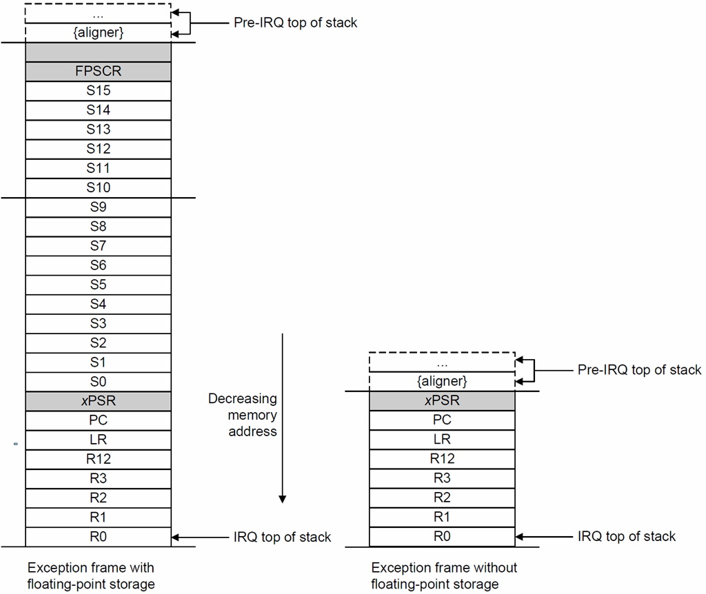
- Push eight registers on the stack: R0, R1, R2, R3, R12, R14 (LR), R15 (PC) and xPSR with R0 on top. If the floating point unit (FPU) is active, an additional 18 words will be pushed on the stack. The stack frame layout is shown as the following diagram
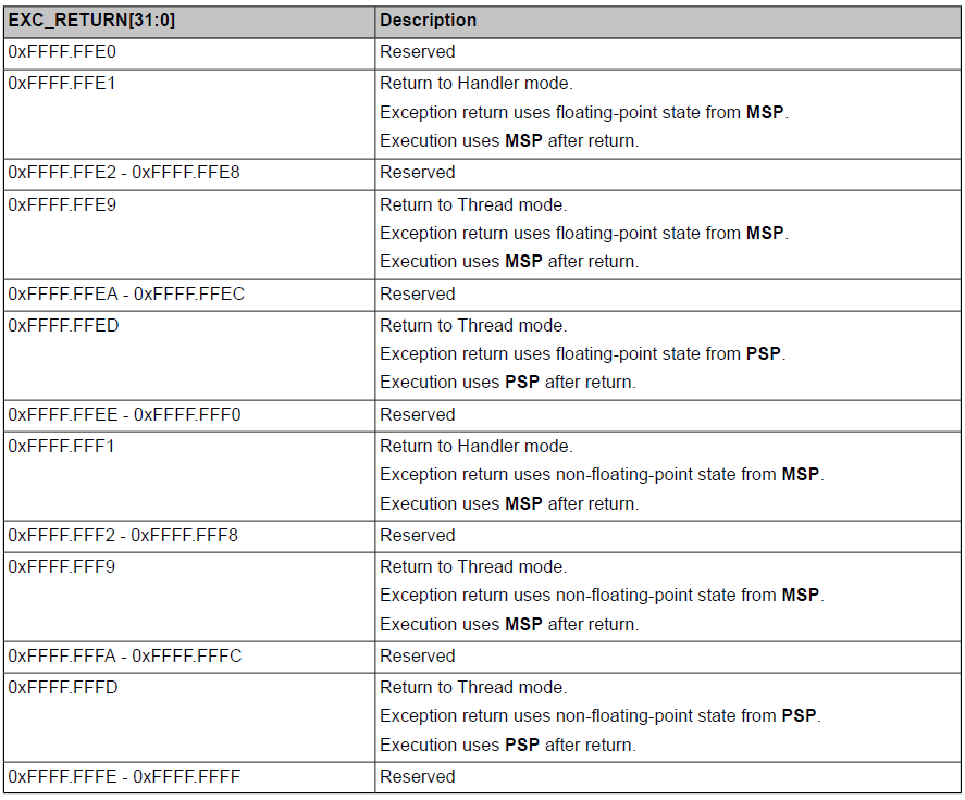
- The EXC_RETURN value is loaded into the R14 (LR) on interrupt entry. The EXC_RETURN bits [31:5] are all set. Bits [4:1] provide information on the return stack, bit [0] is always 1 on Cortex-M meaning Thumb mode. Click here to see the detail EXC_RETURN values.
- The xPSR [7:0] (IPSR ISR Number) is set to the vector number being processed
- The R15 (PC) is loaded with the address of the ISR (vector)
Nested Vectored Interrupt Controller, NVIC
Interrupts on the Cortex-M are controlled by the Nested Vectored Interrupt Controller (NVIC). The NVIC supports:
- 78 interrupts
- A programmable priority level of 0 ~ 7 for each interrupt
A higher level corresponds to a lower priority, so level 0 is the highest interrupt priority - Grouping of priority values into group priority and sub-priority fields
This grouping divides each interrupt priority register entry into two fields:- An upper field that defines the group priority
- A lower field that defines a sub-priority within the group
- Interrupt tail-chaining
This mechanism speeds up exception servicing. On completion of an exception handler, if there is a pending exception that meets the requirements for exception entry, the stack pop is skipped and control transfers to the new exception handler. - An external Non-maskable interrupt (NMI)
The following definitions for NVIC registers are used in Keil μVision:
- NVIC->IP[240]: Interrupt Priority Register NVIC_PRIn (RW)
- NVIC->ISER[8]: Interrupt Set Enable Register NVIC_ENn (RW)
- NVIC->ICER[8]: Interrupt Clear Enable Register NVIC_DISn (RW)
- NVIC->ISPR[8]: Interrupt Set Pending Register NVIC_PENDn (RW)
- NVIC->ICPR[8]: Interrupt Clear Pending Register NVIC_UNPENDn (RW)
- NVIC->IABR[8]: Interrupt Active bit Register NVIC_ACTIVEn (WO)
- NVIC->STIR: Software Trigger Interrupt Register NVIC_SWTRIG (WO)
Interrupt Vectors
Each interrupt (including exceptions, resets, software interrupts, and hardware interrupts) has an associated 32-bit vector that points to the memory location where the ISR handling the interrupt is located.
In the Keil C, the vectors are defined in the Startup.s file.
EK-TM4C123GXL LaunchPad
The vector table contains the reset value of the stack pointer and the start address, also called exception vectors. The vector table is constructed using the vector address shown in next two tabs. The last-significant bit of each vector must be 1, indicating that the interrupt handler is Thumb code.
Interrupt Vectors
Table 1. Exception Types
| Exception Type | Vector Number | Priority | Vector Address | Interrupt Handlers (Keil μVision) | Activation |
| – | 0 | – | 0x0000.0000 | Top of Stack | |
| Reset | 1 | -3 (hightest) | 0x0000.0004 | void Reset_Handler(); | Asynchronous |
| NMI | 2 | -2 | 0x0000.0008 | void NMI_Handler(); | Asynchronous |
| Hard Fault | 3 | -1 | 0x0000.000C | void HardFault_Handler(); | |
| Memory Management | 4 | Programmable (SYSPRI1) | 0x0000.0010 | void MemManage_Handler(); | Synchronous |
| BUS Fault | 5 | Programmable (SYSPRI1) | 0x0000.0014 | void BusFault_Handler(); | Synchronous when precise and Asynchronous when imprecise |
| Usage Fault | 6 | Programmable (SYSPRI1) | 0x0000.0018 | void UsageFault_Handler(); | Synchronous |
| – | 7 ~ 10 | – | – | Reserved | |
| SVC Fault | 11 | Programmable (SYSPRI1) | 0x0000.002C | void SVC_Handler(); | Synchronous |
| Debug Monitor | 12 | Programmable (SYSPRI1) | 0x0000.0030 | void DebugMon_Handler(); | Synchronous |
| – | 13 | – | – | Reserved | |
| PendSV | 14 | Programmable (SYSPRI1) | 0x0000.0038 | void PendSV_Handler(); | Asynchronous |
| SysTick | 15 | Programmable (SYSPRI1) | 0x0000.003C | void SysTick_Handler(); | Asynchronous |
| Interrupts | 16 and above | Programmable (PRIn) | 0x0000.0040 and above | Asynchronous |
Interrupts Table
| Vector Number to IPSR Register | Interrupt Number (Bit in Interrupt Registers) |
Vector Address | Description | Interrupt Handlers (Keil μVision) |
| 0 ~ 15 | – | 0x0000.0000 ~ 0x0000.003C | Processor exceptions | |
| 16 | 0 | 0x0000.0040 | GPIO Port A | void GPIOA_Handler(); |
| 17 | 1 | 0x0000.0044 | GPIO Port B | void GPIOB_Handler(); |
| 18 | 2 | 0x0000.0048 | GPIO Port C | void GPIOC_Handler(); |
| 19 | 3 | 0x0000.004C | GPIO Port D | void GPIOD_Handler(); |
| 20 | 4 | 0x0000.0050 | GPIO Port E | void GPIOE_Handler(); |
| 21 | 5 | 0x0000.0054 | UART0 Rx and Tx | void UART0_Handler(); |
| 22 | 6 | 0x0000.0058 | UART1 Rx and Tx | void UART1_Handler(); |
| 23 | 7 | 0x0000.005C | SSI0 Rx and Tx | void SSI0_Handler(); |
| 24 | 8 | 0x0000.0060 | I2C0 Master and Slave | void I2C0_Handler(); |
| 25 | 9 | 0x0000.0064 | PWM0 Fault | void PWM_FAULT_Handler(); |
| 26 | 10 | 0x0000.0068 | PWM0 Generator 0 | void PWM0_0_Handler(); |
| 27 | 11 | 0x0000.006C | PWM0 Generator 1 | void PWM0_1_Handler(); |
| 28 | 12 | 0x0000.0070 | PWM0 Generator 2 | void PWM0_2_Handler(); |
| 29 | 13 | 0x0000.0074 | QEI0 Quadrature Encoder 0 | void QEI0_Handler(); |
| 30 | 14 | 0x0000.0078 | ADC0 Sequence 0 | void ADC0SS0_Handler(); |
| 31 | 15 | 0x0000.007C | ADC0 Sequence 1 | void ADC0SS1_Handler(); |
| 32 | 16 | 0x0000.0080 | ADC0 Sequence 2 | void ADC0SS2_Handler(); |
| 33 | 17 | 0x0000.0084 | ADC0 Sequence 3 | void ADC0SS3_Handler(); |
| 34 | 18 | 0x0000.0088 | Watchdog Timers 0 and 1 | void WDT0_Handler(); |
| 35 | 19 | 0x0000.008C | 16/32-Bit Timer 0A | void TIMER0A_Handler(); |
| 36 | 20 | 0x0000.0090 | 16/32-Bit Timer 0B | void TIMER0B_Handler(); |
| 37 | 21 | 0x0000.0094 | 16/32-Bit Timer 1A | void TIMER1A_Handler(); |
| 38 | 22 | 0x0000.0098 | 16/32-Bit Timer 1B | void TIMER1B_Handler(); |
| 39 | 23 | 0x0000.009C | 16/32-Bit Timer 2A | void TIMER2A_Handler(); |
| 40 | 24 | 0x0000.00A0 | 16/32-Bit Timer 2B | void TIMER2B_Handler(); |
| 41 | 25 | 0x0000.00A4 | Analog Comparator 0 | void COMP0_Handler(); |
| 42 | 26 | 0x0000.00A8 | Analog Comparator 1 | void COMP1_Handler(); |
| 43 | 27 | – | Reserved | |
| 44 | 28 | 0x0000.00B0 | System Control (PLL, OSC, BO) | void SYSCTL_Handler(); |
| 45 | 29 | 0x0000.00B4 | Flash Memory Control and EEPROM Control | void FLASH_Handler(); |
| 46 | 30 | 0x0000.00B8 | GPIO Port F | void GPIOF_Handler(); |
| 47 ~ 48 | 31 ~ 32 | – | Reserved | |
| 49 | 33 | 0x0000.00C4 | UART2 Rx and Tx | void UART2_Handler(); |
| 50 | 34 | 0x0000.00C8 | SSI1 Rx and Tx | void SSI1_Handler(); |
| 51 | 35 | 0x0000.00CC | 16/32-Bit Timer 3A | void TIMER3A_Handler(); |
| 52 | 36 | 0x0000.00D0 | 16/32-Bit Timer 3B | void TIMER3B_Handler(); |
| 53 | 37 | 0x0000.00D4 | I2C1 Master and Slave | void I2C1_Handler(); |
| 54 | 38 | 0x0000.00D8 | QEI1 Quadrature Encoder 1 | void QEI1_Handler(); |
| 55 | 39 | 0x0000.00DC | CAN0 | void CAN0_Handler(); |
| 56 | 40 | 0x0000.00E0 | CAN1 | void CAN1_Handler(); |
| 57 ~ 58 | 41 ~ 42 | – | Reserved | |
| 59 | 43 | 0x0000.00EC | Hibernation Module | |
| 60 | 44 | 0x0000.00F0 | USB | void USB0_Handler(); |
| 61 | 45 | 0x0000.00F4 | PWM0 Generator 3 | void PWM0_3_Handler(); |
| 62 | 46 | 0x0000.00F8 | μDMA Software | void UDMA_Handler(); |
| 63 | 47 | 0x0000.00FC | μDMA Error | void UDMAERR_Handler(); |
| 64 | 48 | 0x0000.0100 | ADC1 Sequence 0 | void ADC1SS0_Handler(); |
| 65 | 49 | 0x0000.0104 | ADC1 Sequence 1 | void ADC1SS1_Handler(); |
| 66 | 50 | 0x0000.0108 | ADC1 Sequence 2 | void ADC1SS2_Handler(); |
| 67 | 51 | 0x0000.010C | ADC1 Sequence 3 | void ADC1SS3_Handler(); |
| 68 ~ 72 | 52 ~ 56 | – | Reserved | |
| 73 | 57 | 0x0000.0124 | SSI2 Rx and Tx | void SSI2_Handler(); |
| 74 | 58 | 0x0000.0128 | SSI3 Rx and Tx | void SSI3_Handler(); |
| 75 | 59 | 0x0000.012C | UART3 Rx and Tx | void UART3_Handler(); |
| 76 | 60 | 0x0000.0130 | UART4 Rx and Tx | void UART4_Handler(); |
| 77 | 61 | 0x0000.0134 | UART5 Rx and Tx | void UART5_Handler(); |
| 78 | 62 | 0x0000.0138 | UART6 Rx and Tx | void UART6_Handler(); |
| 79 | 63 | 0x0000.013C | UART7 Rx and Tx | void UART7_Handler(); |
| 80 ~ 83 | 64 ~ 67 | – | Reserved | |
| 84 | 68 | 0x0000.0150 | I2C2 Master and Slave | void I2C2_Handler(); |
| 85 | 69 | 0x0000.0154 | I2C3 Master and Slave | void I2C3_Handler(); |
| 86 | 70 | 0x0000.0158 | 16/32-Bit Timer 4A | void TIMER4A_Handler(); |
| 87 | 71 | 0x0000.015C | 16/32-Bit Timer 4B | void TIMER4B_Handler(); |
| 88 ~ 107 | 72 ~ 91 | – | Reserved | |
| 108 | 92 | 0x0000.01B0 | 16/32-Bit Timer 5A | void TIMER5A_Handler(); |
| 109 | 93 | 0x0000.01B4 | 16/32-Bit Timer 5B | void TIMER5B_Handler(); |
| 110 | 94 | 0x0000.01B8 | 32/64-Bit Wide Timer 0A | void WTIMER0A_Handler(); |
| 111 | 95 | 0x0000.01BC | 32/64-Bit Wide Timer 0B | void WTIMER0B_Handler(); |
| 112 | 96 | 0x0000.01C0 | 32/64-Bit Wide Timer 1A | void WTIMER1A_Handler(); |
| 113 | 97 | 0x0000.01C4 | 32/64-Bit Wide Timer 1B | void WTIMER1B_Handler(); |
| 114 | 98 | 0x0000.01C8 | 32/64-Bit Wide Timer 2A | void WTIMER2A_Handler(); |
| 115 | 99 | 0x0000.01CC | 32/64-Bit Wide Timer 2B | void WTIMER2B_Handler(); |
| 116 | 100 | 0x0000.01D0 | 32/64-Bit Wide Timer 3A | void WTIMER3A_Handler(); |
| 117 | 101 | 0x0000.01D4 | 32/64-Bit Wide Timer 3B | void WTIMER3B_Handler(); |
| 118 | 102 | 0x0000.01D8 | 32/64-Bit Wide Timer 4A | void WTIMER4A_Handler(); |
| 119 | 103 | 0x0000.01DC | 32/64-Bit Wide Timer 4B | void WTIMER4B_Handler(); |
| 120 | 104 | 0x0000.01E0 | 32/64-Bit Wide Timer 5A | void WTIMER5A_Handler(); |
| 121 | 105 | 0x0000.01E4 | 32/64-Bit Wide Timer 5B | void WTIMER5B_Handler(); |
| 122 | 106 | 0x0000.01E8 | System Exception (FPU) (imprecise) | void FPU_Handler(); |
| 123 ~ 149 | 107 ~ 133 | – | Reserved | |
| 150 | 134 | 0x0000.02 | PWM1 Generator 0 | void PWM1_0_Handler(); |
| 151 | 135 | 0x0000.02 | PWM1 Generator 1 | void PWM1_1_Handler(); |
| 152 | 136 | 0x0000.02 | PWM1 Generator 2 | void PWM1_2_Handler(); |
| 153 | 137 | 0x0000.02 | PWM1 Generator 3 | void PWM1_3_Handler(); |
| 154 | 138 | 0x0000.02 | PWM1 Fault | void PWM1_FAULT_Handler(); |
EK-TM4C1294XL LaunchPad
The vector table contains the reset value of the stack pointer and the start address, also called exception vectors. The vector table is constructed using the vector address shown in next two tabs. The last-significant bit of each vector must be 1, indicating that the interrupt handler is Thumb code.
Interrupt Vectors
Table 1. Exception Types
| Exception Type | Vector Number | Priority | Vector Address | Interrupt Handlers (Keil μVision) | Activation |
| – | 0 | – | 0x0000.0000 | Top of Stack | |
| Reset | 1 | -3 (hightest) | 0x0000.0004 | void Reset_Handler(); | Asynchronous |
| NMI | 2 | -2 | 0x0000.0008 | void NMI_Handler(); | Asynchronous |
| Hard Fault | 3 | -1 | 0x0000.000C | void HardFault_Handler(); | |
| Memory Management | 4 | Programmable (SYSPRI1) | 0x0000.0010 | void MemManage_Handler(); | Synchronous |
| BUS Fault | 5 | Programmable (SYSPRI1) | 0x0000.0014 | void BusFault_Handler(); | Synchronous when precise and Asynchronous when imprecise |
| Usage Fault | 6 | Programmable (SYSPRI1) | 0x0000.0018 | void UsageFault_Handler(); | Synchronous |
| – | 7 ~ 10 | – | – | Reserved | |
| SVCall | 11 | Programmable (SYSPRI1) | 0x0000.002C | void SVC_Handler(); | Synchronous |
| Debug Monitor | 12 | Programmable (SYSPRI1) | 0x0000.0030 | void DebugMon_Handler(); | Synchronous |
| – | 13 | – | – | Reserved | |
| PendSV | 14 | Programmable (SYSPRI1) | 0x0000.0038 | void PendSV_Handler(); | Asynchronous |
| SysTick | 15 | Programmable (SYSPRI1) | 0x0000.003C | void SysTick_Handler(); | Asynchronous |
| Interrupts | 16 and above | Programmable (PRIn) | 0x0000.0040 and above | Asynchronous |
Interrupts Table
| Vector Number to IPSR Register | Interrupt Number (Bit in Interrupt Registers) |
Vector Address | Description | Interrupt Handlers (Keil μVision) |
| 0 ~ 15 | – | 0x0000.0000 ~ 0x0000.003C | Processor exceptions | |
| 16 | 0 | 0x0000.0040 | GPIO Port A | void GPIOA_Handler(); |
| 17 | 1 | 0x0000.0044 | GPIO Port B | void GPIOB_Handler(); |
| 18 | 2 | 0x0000.0048 | GPIO Port C | void GPIOC_Handler(); |
| 19 | 3 | 0x0000.004C | GPIO Port D | void GPIOD_Handler(); |
| 20 | 4 | 0x0000.0050 | GPIO Port E | void GPIOE_Handler(); |
| 21 | 5 | 0x0000.0054 | UART0 Rx and Tx | void UART0_Handler(); |
| 22 | 6 | 0x0000.0058 | UART1 Rx and Tx | void UART1_Handler(); |
| 23 | 7 | 0x0000.005C | SSI0 Rx and Tx | void SSI0_Handler(); |
| 24 | 8 | 0x0000.0060 | I2C0 Master and Slave | void I2C0_Handler(); |
| 25 | 9 | 0x0000.0064 | PWM0 Fault | void PWM0_FAULT_Handler(); |
| 26 | 10 | 0x0000.0068 | PWM0 Generator 0 | void PWM0_0_Handler(); |
| 27 | 11 | 0x0000.006C | PWM0 Generator 1 | void PWM0_1_Handler(); |
| 28 | 12 | 0x0000.0070 | PWM0 Generator 2 | void PWM0_2_Handler(); |
| 29 | 13 | 0x0000.0074 | QEI0 Quadrature Encoder 0 | void QEI0_Handler(); |
| 30 | 14 | 0x0000.0078 | ADC0 Sequence 0 | void ADC0SS0_Handler(); |
| 31 | 15 | 0x0000.007C | ADC0 Sequence 1 | void ADC0SS1_Handler(); |
| 32 | 16 | 0x0000.0080 | ADC0 Sequence 2 | void ADC0SS2_Handler(); |
| 33 | 17 | 0x0000.0084 | ADC0 Sequence 3 | void ADC0SS3_Handler(); |
| 34 | 18 | 0x0000.0088 | Watchdog Timers 0 and 1 | void WDT0_Handler(); |
| 35 | 19 | 0x0000.008C | 16/32-Bit Timer 0A | void TIMER0A_Handler(); |
| 36 | 20 | 0x0000.0090 | 16/32-Bit Timer 0B | void TIMER0B_Handler(); |
| 37 | 21 | 0x0000.0094 | 16/32-Bit Timer 1A | void TIMER1A_Handler(); |
| 38 | 22 | 0x0000.0098 | 16/32-Bit Timer 1B | void TIMER1B_Handler(); |
| 39 | 23 | 0x0000.009C | 16/32-Bit Timer 2A | void TIMER2A_Handler(); |
| 40 | 24 | 0x0000.00A0 | 16/32-Bit Timer 2B | void TIMER2B_Handler(); |
| 41 | 25 | 0x0000.00A4 | Analog Comparator 0 | void COMP0_Handler(); |
| 42 | 26 | 0x0000.00A8 | Analog Comparator 1 | void COMP1_Handler(); |
| 43 | 27 | 0x0000.00AC | Analog Comparator 2 | void COMP2_Handler(); |
| 44 | 28 | 0x0000.00B0 | System Control (PLL, OSC, BO) | void SYSCTL_Handler(); |
| 45 | 29 | 0x0000.00B4 | Flash Memory Control | void FLASH_Handler(); |
| 46 | 30 | 0x0000.00B8 | GPIO Port F | void GPIOF_Handler(); |
| 47 | 31 | 0x0000.00BC | GPIO Port G | void GPIOG_Handler(); |
| 48 | 32 | 0x0000.00C0 | GPIO Port H | void GPIOH_Handler(); |
| 49 | 33 | 0x0000.00C4 | UART2 Rx and Tx | void UART2_Handler(); |
| 50 | 34 | 0x0000.00C8 | SSI1 Rx and Tx | void SSI1_Handler(); |
| 51 | 35 | 0x0000.00CC | 16/32-Bit Timer 3A | void TIMER3A_Handler(); |
| 52 | 36 | 0x0000.00D0 | 16/32-Bit Timer 3B | void TIMER3B_Handler(); |
| 53 | 37 | 0x0000.00D4 | I2C1 Master and Slave | void I2C1_Handler(); |
| 54 | 38 | 0x0000.00D8 | CAN0 | void CAN0_Handler(); |
| 55 | 39 | 0x0000.00DC | CAN1 | void CAN1_Handler(); |
| 56 | 40 | 0x0000.00E0 | Ethernet MAC | void ETH_Handler(); |
| 57 | 41 | 0x0000.00E4 | Hibernate | void HIB_Handler(); |
| 58 | 42 | 0x0000.00E8 | USB MAC | void USB0_Handler(); |
| 59 | 43 | 0x0000.00EC | PWM Generator 3 | void PWM0_3_Handler(); |
| 60 | 44 | 0x0000.00F0 | μDMA 0 Software | void UDMA_Handler(); |
| 61 | 45 | 0x0000.00F4 | μDMA 0 Error | void UDMAERR_Handler(); |
| 62 | 46 | 0x0000.00F8 | ADC1 Sequence 0 | void ADC1SS0_Handler(); |
| 63 | 47 | 0x0000.00FC | ADC1 Sequence 1 | void ADC1SS1_Handler(); |
| 64 | 48 | 0x0000.0100 | ADC1 Sequence 2 | void ADC1SS2_Handler(); |
| 65 | 49 | 0x0000.0104 | ADC1 Sequence 3 | void ADC1SS3_Handler(); |
| 66 | 50 | 0x0000.0108 | EBI0 External Bus Interface 0 | void EBI0_Handler(); |
| 67 | 51 | 0x0000.010C | GPIO Port J | void GPIOJ_Handler(); |
| 68 | 52 | 0x0000.0110 | GPIO Port K | void GPIOK_Handler(); |
| 69 | 53 | 0x0000.0114 | GPIO Port L | void GPIOL_Handler(); |
| 70 | 54 | 0x0000.0118 | SSI2 Rx and Tx | void SSI2_Handler(); |
| 71 | 55 | 0x0000.011C | SSI3 Rx and Tx | void SSI3_Handler(); |
| 72 | 56 | 0x0000.0120 | UART3 Rx and Tx | void UART3_Handler(); |
| 73 | 57 | 0x0000.0124 | UART4 Rx and Tx | void UART4_Handler(); |
| 74 | 58 | 0x0000.0128 | UART5 Rx and Tx | void UART5_Handler(); |
| 75 | 59 | 0x0000.012C | UART6 Rx and Tx | void UART6_Handler(); |
| 76 | 60 | 0x0000.0130 | UART7 Rx and Tx | void UART7_Handler(); |
| 77 | 61 | 0x0000.0134 | I2C2 Master and Slave | void I2C2_Handler(); |
| 78 | 62 | 0x0000.0138 | I2C3 Master and Slave | void I2C3_Handler(); |
| 79 | 63 | 0x0000.013C | Timer 4A | void TIMER4A_Handler(); |
| 80 | 64 | 0x0000.0140 | Timer 4B | void TIMER4B_Handler(); |
| 81 | 65 | 0x0000.0144 | Timer 5A | void TIMER5A_Handler(); |
| 82 | 66 | 0x0000.0148 | Timer 5B | void TIMER5B_Handler(); |
| 83 | 67 | 0x0000.014C | Floating-Point Exception (imprecise) | void FPU_Handler(); |
| 84 ~ 85 | 68 ~ 69 | Reserved | ||
| 86 | 70 | 0x0000.0158 | I2C4 Master and Slave | void I2C4_Handler(); |
| 87 | 71 | 0x0000.015C | I2C5 Master and Slave | void I2C5_Handler(); |
| 88 | 72 | 0x0000.0160 | GPIO Port M | void GPIOM_Handler(); |
| 89 | 73 | 0x0000.0164 | GPIO Port N | void GPION_Handler(); |
| 90 | 74 | – | Reserved | |
| 91 | 75 | 0x0000.016C | Tamper | void TAMPER_Handler(); |
| 92 | 76 | 0x0000.0170 | GPIO Port P (Summary or P0) | void GPIOP0_Handler(); |
| 93 | 77 | 0x0000.0174 | GPIO Port P1 | void GPIOP1_Handler(); |
| 94 | 78 | 0x0000.0178 | GPIO Port P2 | void GPIOP2_Handler(); |
| 95 | 79 | 0x0000.017C | GPIO Port P3 | void GPIOP3_Handler(); |
| 96 | 80 | 0x0000.0180 | GPIO Port P4 | void GPIOP4_Handler(); |
| 97 | 81 | 0x0000.0184 | GPIO Port P5 | void GPIOP5_Handler(); |
| 98 | 82 | 0x0000.0188 | GPIO Port P6 | void GPIOP6_Handler(); |
| 99 | 83 | 0x0000.018C | GPIO Port P7 | void GPIOP7_Handler(); |
| 100 | 84 | 0x0000.0190 | GPIO Port Q (Summary or Q0) | void GPIOQ0_Handler(); |
| 101 | 85 | 0x0000.0194 | GPIO Port Q1 | void GPIOQ1_Handler(); |
| 102 | 86 | 0x0000.0198 | GPIO Port Q2 | void GPIOQ2_Handler(); |
| 103 | 87 | 0x0000.019C | GPIO Port Q3 | void GPIOQ3_Handler(); |
| 104 | 88 | 0x0000.01A0 | GPIO Port Q4 | void GPIOQ4_Handler(); |
| 105 | 89 | 0x0000.01A4 | GPIO Port Q5 | void GPIOQ5_Handler(); |
| 106 | 90 | 0x0000.01A8 | GPIO Port Q6 | void GPIOQ6_Handler(); |
| 107 | 91 | 0x0000.01AC | GPIO Port Q7 | void GPIOQ7_Handler(); |
| 108~113 | 92-97 | – | Reserved | |
| 114 | 98 | 0x0000.01C8 | 16/32-Bit Timer 6A | void TIMER6A_Handler(); |
| 115 | 99 | 0x0000.01CC | 16/32-Bit Timer 6B | void TIMER6B_Handler(); |
| 116 | 100 | 0x0000.01D0 | 16/32-Bit Timer 7A | void TIMER7A_Handler(); |
| 117 | 101 | 0x0000.01D4 | 16/32-Bit Timer 7B | void TIMER7B_Handler(); |
| 118 | 102 | 0x0000.01D8 | I2C6 Master and Slave | void I2C6_Handler(); |
| 119 | 103 | 0x0000.01DC | I2C7 Master and Slave | void I2C7_Handler(); |
| 120~124 | 104~108 | – | Reserved | |
| 125 | 109 | 0x0000.01F4 | I2C8 Master and Slave | void I2C8_Handler(); |
| 126 | 110 | 0x0000.01F8 | I2C9 Master and Slave | void I2C9_Handler(); |
| 127 ~ 129 | 111 ~ 113 | – | Reserved |
Interrupt Priority
The NVIC_PRIn_R registers provide 3-bit priority fields for each interrupt. This allows the interrupt priority level for each device from 0 to 7, with 0 being the highest priority.
n = Integer( Interrupt Number / 4 )
p = ( Interrupt Number % 4 ) =
0: INTA (bit.7 to bit.5)
1: INTB (bit.15 to bit.13)
2: INTC (bit.23 to bit.21)
3: INTD (bit.31 to bit.29)
| Bits in PRIn Register | 31 ~ 29 | 28 ~ 24 | 23 ~ 21 | 20 ~ 16 | 15 ~ 13 | 12 ~ 8 | 7 ~ 5 | 4 ~ 0 |
| INTD | 00000 | INTC | 00000 | INTB | 00000 | INTA | 00000 | |
| Interrupt Number | Interrupt [4n + 3] | Interrupt [4n + 2] | Interrupt [4n + 1] | Interrupt [4n] |
NVIC->IP[n] |= (PriorityNumber << INTp_BIT);
For example, if the system needs to setup priority for PWM0 Generator 0 interrupt.The interrupt number of PWM0 Generator 0 is 10. Calculate n value:
n = Integer( 10 / 4 ) = 2 ==> PRI2 register
p = ( 10 % 4) = 2 ==> INTC
The priority level must be write to NVIC_PRI2_R [23:21] register.
The following C code shows how to set priority 3 for ADC Sequence 0 interrupt :
NVIC->IP[2] |= (3UL << 21);
Enable Interrupt Through NVIC
After set the priority for the interrupt, then the interrupt must be enabled in the NVIC_ENm_R register.
Each NVIC_ENm_R register has 32-bits, and each bit controls one interrupt number. Using the following formula to find out NVIC_ENm_R register number and the bit number to enable the interrupt on NVIC.
m = interrupt number / 32
b = interrupt number % 32
NVIC->ISER[m] |= (1UL << b);
For example, too enable ADC Sequence 0 interrupt on the NVIC. The interrupt number of ADC Sequence 0 is 48.
m = 48 / 32 =1 ==> EN1 register
b = 48 % 32 = 16 ==> bit 16
You need to set NVIC_EN1_R [16] = 1 to enable interrupt for ADC Sequence 0.
The following C code shows how to enable interrupt for ADC Sequence 0 :
NVIC->ISER[1] = (1UL << 16);
Disable Interrupt Through NVIC
To disable interrupts, you need to write '1' to the corresponding bit in the NVIC_DISm_R register.
NVIC->ICER[1] = (1UL << 16);
Interrupt Service Routine or Interrupt Handler
You need to implement an ISR or Handler to process the interrupt request. The following code shows an ISR for GPIO Port B that looks like a regular function with no input parameters and no return value.
void GPIOB_Haqndler(void) {
// Your ISR code for GPIO Port B here
}
Keil μVision has defined the handler name for each interrupt request. You must use exactly the same handler name as defined. Check the name of the Interrupt Handler from the above Interrupt Table (or find it in the startup_TM4Cxx.s file).
Most of ISR must acknowledge the interrupt in software by clearing the flag that caused the interrupt. After clear the interrupt trigger flag, the peripheral can accept the next interrupt request to CPU.
GPIO Interrupts
GPIO Interrupts
The interrupt functions of each GPIO port are controlled by a set of seven registers: GPIOIS, GPIOIBE, GPIOIEV, GPIOIM, GPIORIS, GPIOMIS, and GPIOICR. These registers are used to select the source of the interrupt, its polarity, and the edge properties. When one or more GPIO inputs cause an interrupt, a single interrupt output is sent to the interrupt controller for the entire GPIO port. For edge-triggered interrupts, software must clear the interrupt to enable any further interrupts. For a level-sensitive interrupt, the external source must hold the level constant for the interrupt to be recognized by the controller.
Three registers define the edge or sense that causes interrupts:
- GPIO Interrupt Sense register, GPIOIS (GPIOn->IS)
- GPIO Interrupt Both Edges register, GPIOIBE (GPIOn->IBE )
- GPIO Interrupt Event register, GPIOIEV (GPIOn->IEV )
Interrupts are enabled/disabled via the GPIO Interrupt Mask (GPIOIM, GPIOn->IM ) register.
When an interrupt condition occurs, the state of the interrupt signal can be viewed in two locations: the GPIO Raw Interrupt Status (GPIORIS, GPIOn->RIS ) and GPIO Masked Interrupt Status (GPIOMIS, GPIOn->MIS ) registers.
- The GPIOMIS register only shows interrupt conditions that are allowed to be passed to the interrupt controller.
- The GPIORIS register indicates that a GPIO pin meets the conditions for an interrupt, but has not necessarily been sent to the interrupt controller.
For a GPIO level-detect interrupt, the interrupt signal generating the interrupt must be held until serviced. Once the input signal deasserts from the interrupt generating logical sense, the corresponding RIS bit in the GPIORIS register clears.
For a GPIO edge-detect interrupt, the RIS bit in the GPIORIS register is cleared by writing a '1' to the corresponding bit in the GPIO Interrupt Clear (GPIOICR, GPIOn->ICR ) register. The corresponding GPIOMIS bit reflects the masked value of the RIS bit.
When programming the interrupt control registers (GPIOIS, GPIOIBE, or GPIOIEV), the interrupts should be masked (GPIOIM cleared). Writing any value to an interrupt control register can generate a spurious interrupt if the corresponding bits are enabled.
Registers
In order to use GPIO interrupts, the GPIO Ports must be configured. After configured the GPIO, the following steps show how to configure the interrupt on the GPIO pins:
- Disable IRQ in the GPIOIM register
- Configure IRQ Type (0=edge, 1=level) in the GPIOIS register
- Configure GPIOIBE (0=single edge, 1=both edge), GPIOIEV (0=low level or falling edge, 1=high level or rising edge)
- Clear the GPIORIS register
- Enable IRQ in the GPIOIM register
- Set priority in the NVIC
- Enable IRQ in the NVIC
Keil C Sample Firmware Code
void Setup_GPIOIRQ()
{
    // Configure GPIO IRQ on PJ0 (Negative Logical Input)
	// 1. Disable IRQ in GPIOIM register
	GPIOJ_AHB->IM &= ~(_PIN0);
	// 2. Configure IRQ Type (0=edge, 1=level) in the GPIOIS register
	GPIOJ_AHB->IS &= ~(_PIN0);
    // 3. Configure GPIOIBE (0=single edge, 1=both edge),
    //    and GPIOIEV (0=low level or falling edge, 1=high level or rising edge)
	GPIOJ_AHB->IBE &= ~(_PIN0);
	GPIOJ_AHB->IEV &= ~(_PIN0);
    // 4. Clear the GPIORIS register
	GPIOJ_AHB->ICR |= _PIN0;
    // 5. Enable IRQ in the GPIOIM register
	GPIOJ_AHB->IM |= _PIN0;
    // 6. Set priority in the NVIC
	NVIC->IP[n] |= (3UL << r);
    // 7. Enable IRQ in the NVIC
	NVIC->ISER[m] |= (1UL << r2);
}
void GPIOJ_Handler()
{
    // 1. Check the PIN, make sure that the IRQ occurred from the PIN you defined
    if ((GPIOJ_AHB->RIS & ____) == ____) {
        // The code for IRQ

        // Then to Clear Interrupt Flag (GPIOJ->ICR)
        GPIOJ_AHB->ICR |= ____;
    }
}
Timer Interrupts
Timer Interrupts
UART Interrupts
UART Interrupts
ADC Interrupts
ADC Interrupts