MAX7219 LED Dot Matrix Display
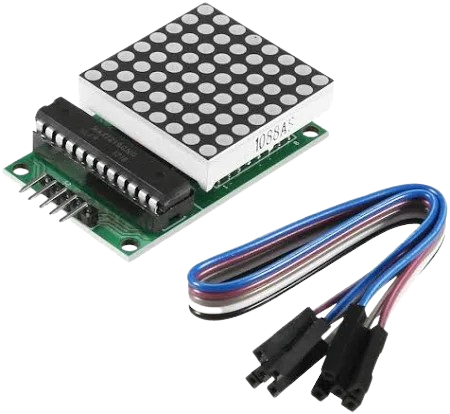
The MAX7219 is a highly integrated serial-input LED driver IC designed to control an 8×8 LED dot-matrix display or eight 7-segment displays using a minimal number of microcontroller pins. It manages multiplexing, current regulation, brightness control, and supports cascading multiple units to form larger display panels.
For LED dot-matrix projects — such as static text, scrolling banners, animations, or indicator panels — the MAX7219 greatly simplifies both wiring and software design.
Hardware Architecture
- LED Dot Matrix Structure
An 8×8 dot-matrix consists of:- 8 rows × 8 columns = 64 LEDs
Each LED is addressed at the intersection of a row and a column. Directly driving 64 LEDs requires many pins and careful multiplexing, so the MAX7219 handles the refresh scanning internally.
- 8 rows × 8 columns = 64 LEDs
- How the MAX7219 Works
- Drives one row at a time at high refresh rates
- Manages LED current and intensity
- Accepts 16-bit serial commands
- Provides eight-digit/row registers for raw LED data
- Handles cascading via DOUT → DIN chaining
- Supports up to eight scanned rows (0 ~ 7)
- Brightness and LED Current
LED current is controlled by:- Hardware – an external RSET resistor attached to the ISET pin
- Software – intensity register (0 ~ 15 brightness levels)
Selecting proper RSET ensures safe LED current and proper brightness.
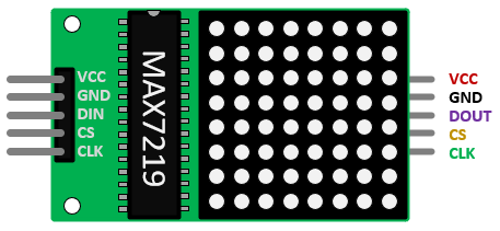
Pinout and Wiring
MAX7219 dot-matrix modules include:
| Pin | Function |
| VCC | +5 V Power |
| GND | Ground |
| DIN | Serial Data Input (MOSI) |
| CS/LOAD | Chip-Select Latch |
| CLK | Serial Clock |
| DOUT | Serial Data Output (for cascading) |
Cascading Multiple Modules
To build wider displays (8×16, 8×32, 8×64, etc.):
- Connect DOUT → DIN of the next module
- All modules share VCC, GND, CLK, and CS
- Send multiple 16-bit frames in sequence to update all cascaded devices

MAX7219 Configuration Registers
The MAX7219 receives 16-bit commands:
- High byte: Register address
- Low byte: Register data
Below are all the important registers required for LED matrix operation:
| Register | Address | Description |
| No-Op | 0x00 | Does nothing; used when cascading |
| Digit 0 ~ 7 | 0x01 ~ 0x08 | Data for each row (8-bit pattern per row) |
| Decode-Mode | 0x09 | Enables/disables Code-B decoding |
| Intensity | 0x0A | Brightness level (0 ~ 15) |
| Scan-Limit | 0x0B | How many rows (digits) are active (0 ~ 7) |
| Shutdown | 0x0C | Controls normal/shutdown mode |
| Display-Test | 0x0F | Turns all segments on for Test |
Preferred Configuration for Dot Matrix
Dot-matrix requires no decode mode, because each bit represents an LED, not a Code-B segment.
Initialization Sequence for LED Dot Matrix
A typical initialization sequence performed after powering the module:
- Enter Shutdown Mode
Address: 0x0C Data: 0x00 Purpose: Blank the display during configuration - Disable Decode Mode (Required for Matrix)
Address: 0x09 Data: 0x00 Enables raw 8-bit row data - Set Scan Limit (Use All 8 Rows)
Address: 0x0B Data: 0x07 Rows 0 ~ 7 active - Set Intensity (Brightness)
Address: 0x0A Data: 0x00 ~ 0x0F Rows 0 ~ 7 active - Optional: Display Test
Address: 0x0F Data: 0x01 → test on, 0x00 → test off - Return to Normal Operation
Address: 0x0C Data: 0x01 Activates display
After initialization, write to Digit Registers (0x01 ~ 0x08) to control LED rows.
Writing to the Display
Each row corresponds to one digit register:
| Row | Register | Meaning |
| Row 0 | 0x01 | Display Row 0 |
| Row 1 | 0x02 | Display Row 2 |
| ... | ... | ... |
| Row 7 | 0x08 | Display Row 7 |
Each row receives 8 bits, where each bit controls one column LED:
Example: 0b10101010 Turns ON columns 7,5,3,1 in that row.
To update the whole display, send row patterns to all eight row registers.
