Lab 02: Digital Multimeter: DC Voltage and DC Current Measurement
Objective
- Measurement of DC current and voltage
- Measurement of voltmeter and ammeter internal resistance
Equipment
Background
Voltmeter
An ideal voltmeter has infinite resistance, which can be considered as an open circuit. Although it is impossible to make a physical voltmeter with infinite resistance, a well-designed voltmeter exhibits a very large internal input resistance.
To determine the internal resistance of the voltmeter, set up the circuit shown in Figure 1. The voltmeter reads the voltage across itself, which includes its internal resistor. The current is given by the equation:
\(I = \frac{{{V_s} - {V_M}}}{R}\)
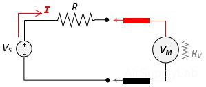
Figure 1: Circuit for Measuring the Resistance of the Voltmeter
Since the circuit has only a single branch, the current flowing through the resistor also flows through the voltmeter. From Ohm's Law, if we know the current (I) and the voltage (VM), we can compute RV:
\({R_V} = \frac{{{V_M}}}{I} = \frac{{{V_M}}}{{\left( {\frac{{{V_S} - {V_M}}}{R}} \right)}} = \frac{{R \times {V_M}}}{{{V_S} - {V_M}}}\)
Ammeter
An ideal ammeter has zero resistance so that the circuit in which it has been placed is not disturbed, and it can be considered as a short circuit. However, all ammeters have some small internal resistance. One way to measure the internal resistance of an ammeter in the circuits is shown as below:
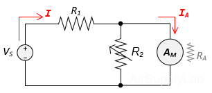
Figure 2: Current Divider Circuit
\[{R_A} = {{{V_S} - {I_A}{R_1}} \over {1 + {{{R_1}} \over {{R_f}}}}} \times {1 \over {{I_A}}}\]
Procedure
Exp #1: Measure DC Resistance of the DMM Voltmeter
- Connect the Digital Multimeter (DMM) to a DC Power Supply as shown below. Set the DC Power Supply to provide 10 V. Set the DMM to DC VOLTS mode and measure the actual output voltage (VS).
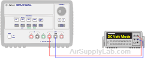
Figure 1: Connect DC Power Supply and Set The Output Voltage to 10 V
Always measure the voltage provided by the power supply with either the oscilloscope or the voltmeter. Do not rely on the digital display on the power supply.
- Connect a Resistance Substitution Box in series between the DC Power Supply and the DMM.

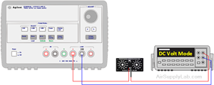
Figure 2: Connect a Resistance Substitution Box in Series - Read the voltage values on the DMM for the following values of series resistance: 1000 KΩ, 470 KΩ, 100 KΩ, 1 KΩ.
- Discount the power, change DMM to ohmmeter mode, and measure the actual resistance values.
- From these readings, use voltage division to calculate RV, the equivalent internal resistance of the voltmeter.
Table 1: Calculation for Internal Resistance of the Voltmeter
Exp #2: Measure DC Resistance of the DMM Ammeter
Ammeters also have an internal electrical resistance. Ideally, an ammeter would have no resistance (0 Ω), so that it would not alter the current flow it is trying to measure. In this exercise, you will measure the DC resistance of the real DMM ammeter.
- Use the DMM to measure a 1 KΩ resistor, then record this value in Table 2.
- Set up the circuit as shown in Figure 3. Using the DMM for the ammeter.
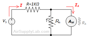
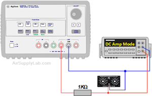
Figure 3: Connection for Ammeter - Set the resistor Rn to 1 MΩ resistance. Record the resistance Rn and the current indicated by the ammeter.
- Adjust Rn to 100 kΩ. In your table, record the resistance Rn and the current indicated by the ammeter.
- Continue to decrease the resistance Rn until the ammeter reading drops by a significant fraction (up to about one-half) of the original value. Record the final resistance Rf and measured current.
- Discount the connection and turn off the Power Supply. Then use the DMM ohmmeter to measure the actual final resistance Rf value. (You will need to connect the DMM cables to “VΩ” and “COM” for this measurement.)
- From these readings, use current division to calculate RA, the equivalent internal resistance of the ammeter.
Questions
- Define "resolution", "accuracy", and "precision" and explain the differences (if any) among these three terms.
- What is the difference between the "nominal" and the "actual" value of an electronic component?
- What is the input resistance of an ideal current-measuring DMM?
- What is the input resistance of an ideal voltage-measuring DMM?
- How must a DMM be connected in a circuit to measure current: In series or in parallel?
- How must a DMM be connected in a circuit to measure voltage: In series or in parallel?
- Under what conditions will the voltage burden or the input resistance of the DMM produce a significant error in current measurement?
