Lesson 07: Gate-Level (Structural) Modeling
Gate-Level Modeling
Gate-level modeling (also known as Structural modeling) can be used to write Verilog codes for small designs. Verilog HDL supports built-in primitive gates modeling. The gates supported are multiple-input, multiple-output, tristate, and pull gates. The multiple-input gates supported are: and, nand, or, nor, xor, and xnor whose number of inputs are two or more, and has only one output. The multiple-output gates supported are buf and not whose number of output is one or more, and has only one input. The language also supports the modeling of tri-state gates which include bufif0, bufif1, notif0, and notif1. These gates have one input, one control signal, and one output. The pull gates supported are pullup and pulldown with a single output (no input) only.
For gate-level modeling, the schematic for the combinational logic circuit must be drawn first.

Figure 1: Schematic
The first step in using gate-level modeling is to check that all wires must have unique names. All the input/output wires have the same name as the I/O port name. In the schematic diagram of Figure 1, the output wires of the NOT and AND gates have no name, and they should be assigned a name. The wire name nc indicates the output wire of the NOT gate, and y0 indicates the output of the AND gate.
In the second step, use logic gates to describe the schematic from left-to-right, top-to-bottom.
Based on the schematic shown in Figure 1, the Verilog code can be written as follows:
module circuit1(a, b, c, f);
input  a, b, c;
output f;

wire  nc, y0;

not U1(nc, c);
and U2(y0, b, nc);
or  U3(f, y0, a);
endmodule
In the gate-level modeling, only the gates and wires can be used in the code.
Gates
The gates have one scalar output and multiple scalar inputs. The first terminal in the list of gate terminals is an output and the other terminals are inputs.
The basic syntax for each type of gates with zero delays is as follows:
and | nand | or | nor | xor | xnor [instance name] (out, in1, …, inN); // [] is optional and | is selection

| Gate | Description | Syntax |
| or | N-input OR gate | or GateName(out, in1, in2, in3, ...); |
| and | N-input AND gate | and GateName(out, in1, in2, in3, ...); |
| xor | N-input XOR gate | or GateName(out, in1, in2, in3, ...); |
| nor | N-input NOR gate | nor GateName(out, in1, in2, in3, ...); |
| nand | N-input NAND gate | nand GateName(out, in1, in2, in3, ...); |
| xnor | N-input XNOR gate | xnor GateName(out, in1, in2, in3, ...); |
Buffer and NOT Gates
The basic syntax for each type of gates with zero delays is as follows:
buf | not [instance name] (out1, out2, …, out2, input);

| Gate | Description | Syntax |
| buf | N-output buffer | buf GateName(out1, out2, ..., in); |
| not | N-output NOT gate | not GateName(out1, out2, ..., in); |
Tri-State Gates
The basic syntax for each type of gates with zero delays is as follows:
bufif0 | bufif1 | notif0 | notif1 [instance name] (outputA, inputB, controlC);

| Gate | Description | Syntax |
| bufif0 | Tri-state buffer with active-low control | bufif0 GateName(out, in, ctrl); |
| bufif1 | Tri-state buffer with active-high control | bufif1 GateName(out, in, ctrl); |
| notif0 | Tri-state NOT gate with active-low control | notif0 GateName(out, in, ctrl); |
| notif1 | Tri-state NOT gate with active-high control | notif1 GateName(out, in, ctrl); |
Pullup and Pulldown for Output Pins
The basic syntax for each type of gates with zero delays is as follows:
pullup | pulldown [instance name] (output A);
The gate-level modeling is useful when a circuit is a simple combinational, as an example a multiplexer. Multiplexer is a simple circuit which connects one of many inputs to an output. In this part, you will create a simple 2-to-1 multiplexer and extend the design to multiple bits.
Gate-Level Modeling of a 4x1 Multiplexer
Write a Verilog description of the 2-to-4 decoder as shown below using gate-level modeling.

module mux_4to1(in0, in1, in2, in3, s0, s1, out);
    input  in0, in1, in2, in3, s0, s1
    output out;

    wire ns0, ns1;
    wire a0, a1, a2, a3;

    not N0(ns0, s0);
    not N1(ns1, s1);
    and G0(a0, ns0, ns1, in0);
    and G1(a1, ns0,  s1, in1);
    and G2(a2,  s0, ns1, in2);
    and G3(a3,  s0,  s1, in3);
    or  G4(out, a0, a1, a2, a3);
endmodule
Gate
Questions
Using gate-level (structural) modeling to solve the following questions.
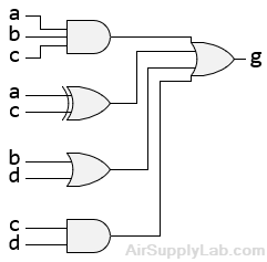
- Write the Verilog module to implement the circuit in the following figure using gate-level modeling.
- Write a Verilog description to implement the circuit of the following figure using gate-level modeling.
