Lesson KB 06: Interfacing Character LCD Display Module with PSoC
HD44780-based character LCD modules are very popular for use on the embedded system because they are cheap and an easy way to have your project show status messages. All HD44780-based character LCD modules are connected through 14 pins -- 8 data pins (D0~D7), three control pins (RS, E, R/W), and three power lines (Vdd, Vss, Vo).
Some LCDs have an LED backlight feature that helps to read the content on the LCD screen during low illumination conditions. So they come with two extra pins for the backlight LED (A, K). The backlight LED can be powered directly from Vdd or connected with a PWM signal to adjust the LED brightness rate by the program.
The LCD module can be fully controlled by an 8-bit interface or a 4-bit interface mode. The PSoC Creator supports a 4-bit interface mode, it requires 6 I/O lines of the PSoC 5LP microcontroller: 4 data lines and two control lines. The connection diagrams between the LCD module and PSoC 5LP development boards are shown below:
For Cypress CY8CKIT-059 Prototyping Kit
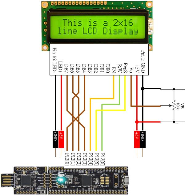
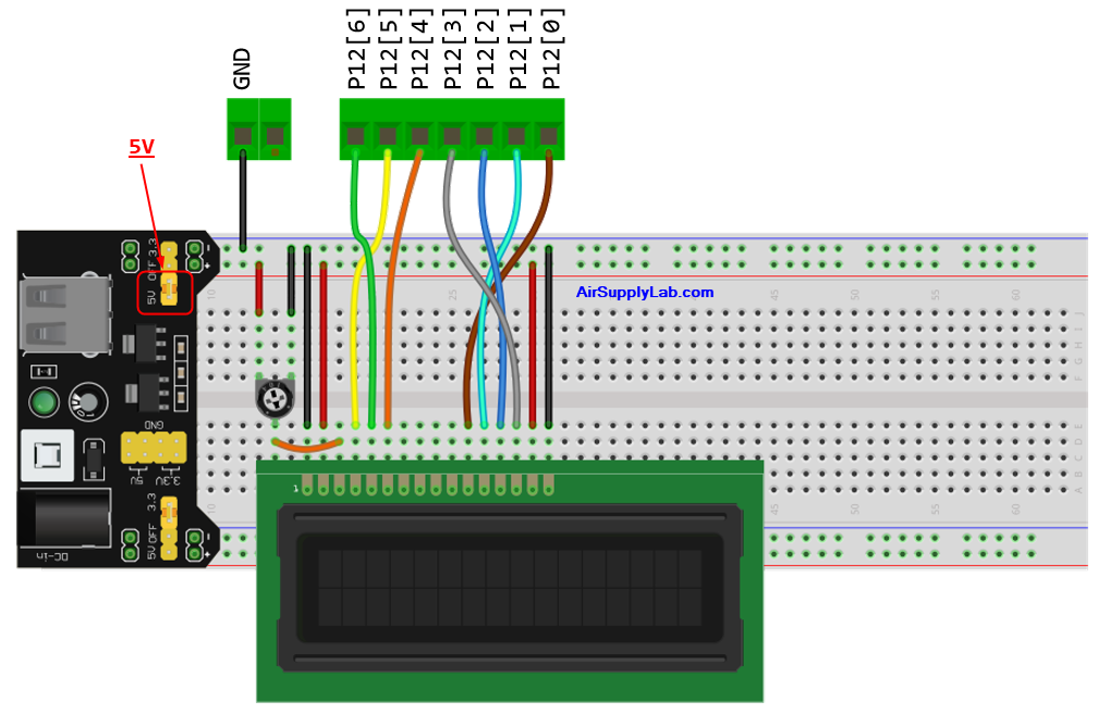
If you use the CY8CKIT-059 PSoC 5LP Prototyping Kit, as shown in the above figure, you need to make a cable and connect the LCD module to P12[6:0].
For EagleSoC Board
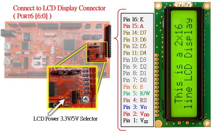
The EagleSoC board already has one 16-pin LCD module connector. You need to solder a 14 or 16-pin male header on your LCD module, then directly plug it onto the connector.
For EagleSoC Mini Board
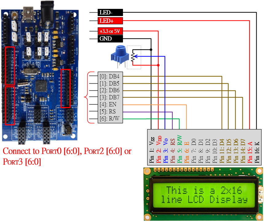
EagleSoC Mini board does not have an LCD module connector, so you have to make a cable with a 10K potentiometer, as shown in the figure above. Then you can connect the cable to either Port0[6:0], Port2[6:0], or Port3[6:0].
If you use another PSoC 5LP development board, you can connect the LCD module with any port. You just follow the bit connection shown in the above diagram and check the schematic diagram of your PSoC 5LP board to make sure the pins you chose are not connected with any capacitor on the board.
Now, launch the PSoC Creator, and start a new PSoC 5LP project. The project name is "myLCD" or any name you like. Please ensure the chip number is the same on the PSoC 5LP chip on your development board.
- In the Component Catalog panel, drag and drop the "Character LCD" component (Display ➤ Character LCD) into your TopDesign.cysch schematic file as shown in Figure 2.
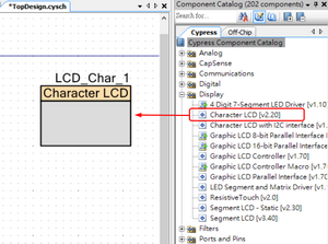
Figure 2: Add the LCD component to your TopDesign layout - Double-click on the LCD component in the TopDesign.cysch to open the configuration dialog. Rename the component name to "LCD", then click OK to save the settings.
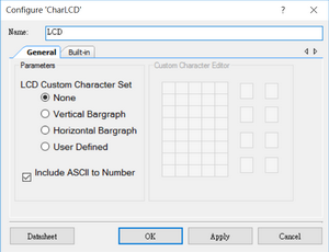
Figure 3: Rename the LCD component to "LCD" - From the Workspace Explorer panel, double-click the CharLCD.cydwr file to open Design-Wide Resources (DWR) panel. In the Pins tab, assign GPIOs to the LCD:LCDPort[6:0]
- For the EagleSoC board, use P6[6:0] port. For the EagleSoC Mini board, use one of the P0[6:0], P2[6:0], or P3[6:0] ports.
- For the Cypress Development board (CY8CKIT-001 or CY8CKIT-050), use the P2[6:0] port
- For the CY8CKIT-059 Prototyping board, use P12[6:0] port
- or, you can choose any [6:0] port, check the board schematic or documentation to make sure that all of the pins on that port do not connect with any capacitors on the board
- Build the design by pressing the Build button or clicking Build ➤ Build CharLCD from the menu to generate source code for the component's API (Application Programming Interface) and compile the project.
- After successfully building and compiling the code (i.e. there are no errors), check the Workspace Explorer panel. You will see that the PSoC Creator generates many files based on the components used in your TopDesign under the Generated_Source folder. Remember, do not change or modify any files inside the Generated_Source folder. The PSoC Creator will automatically maintain and update those files whenever you make a change in your TopDesign file.
- Before we start writing the code to control the LCD module, you need to study the documentation for the LCD API. Right-click on the LCD component in your TopDesign file, then select "Open Datasheet..." to open the datasheet for the LCD component.
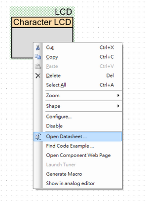
Figure 4: Open the Datasheet - From the datasheet, we find that the LCD component must be initialized before we use it in the code, and there are also some useful API functions that we will use in the code. Therefore, please study the API functions before you continue with this step.
- Double-click the main.c file from the Workspace Explorer panel in your project's Source Files folder. Place the following code in your main.c source file.
int main()
{
    uint8_t     counter = 0;

    CyGlobalIntEnable; /* Enable global interrupts. */

    /* Place your initialization/startup code here. */
    LCD_Start();
    LCD_ClearDisplay();
    LCD_Position(0, 0);
    LCD_PrintString("EE-4450");

    for (;;;){
        /* Place your application code here. */
        LCD_PrintNumber(counter);
        counter++;
        CyDelay(500);
    }
}
Code 1: Display the Counter Value on Character LCD - Then, you need to build the code again. If there are no errors, you can program the code to the PSoC 5LP development board by pressing the Program button or selecting Debug ➤ Program from the menu and then check the result on the LCD screen.
Now, the LCD shows the "EE-4450" string, and every 100ms, it shows the counter's value on the screen. However, very soon, you will find that the LCD screen will be filled with the counter value, and it will not be easy to recognize the current counter value.
Therefore, you will need to modify the code to display the counter value at a certain position by adding the LCD_Position() API function before displaying the counter value, as shown in Code 2.
int main()
{
    uint8_t     counter = 0;

    CyGlobalIntEnable; /* Enable global interrupts. */

    /* Place your initialization/startup code here. */
    LCD_Start();
    LCD_ClearDisplay();
    LCD_Position(0, 0);
    LCD_PrintString("EE-4450");

    for (;;;){
        /* Place your application code here. */
        LCD_Position(0,6);
        LCD_PrintString("Counter: ");
        LCD_PrintNumber(counter);
        counter++;
        CyDelay(500);
    }
}
Code 2: Display the Counter Value at the Specified LCD Position
Now, the value on the LCD screen seems more readable than before. After the counter value goes over 255, the new value should be 0 and continue to increment. However, when the new counter value is displayed on the screen, the second and/or third digits are not erased; instead, the value on the screen becomes 055, 155, 255, 355, ..... 955, 105,...
One easy solution to solve this problem is by adding a few "space" characters after the counter number. The number of digits for the counter ranges from one to three, so we just need to display two "space" characters after displaying the counter value.
    for (;;;){
        /* Place your application code here. */
        LCD_Position(0, 6);
        LCD_PrintString("Counter: ");
        LCD_PrintNumber(counter);
        LCD_PrintString("  ")
        counter++;
        CyDelay(500);
    }
Code 3: Remove Unnecessary Values by Adding Few "Space" Characters