Lab 11: Thevenin's Theorem
Objectives
- Become aware of an experimental procedure to determine VTh and RTh.
- Validate Thévenin’s theorem through experimental measurements using two methods.
- Validate the maximum power transfer relation for a Thévenin circuit.
Equipments
Background
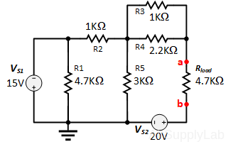
Through the use of Thévenin’s theorem, a complex two-terminal, linear, multisource DC circuit can be replaced by one having a single source and resistor. The Thévenin equivalent circuit consists of a single DC source referred to as the Thévenin voltage and a single fixed resistor called the Thévenin resistance. The Thévenin voltage is the open-circuit voltage across the terminal points of the load. The Thévenin resistance can be calculated using two methods:
- Method-1: Determine the Thévenin resistance when all sources deactivated.
- Method-2: Determine the Thévenin resistance using the ratio of the Thévenin voltage to the short circuit current of the load resistance – vOC / iSC.
Procedure
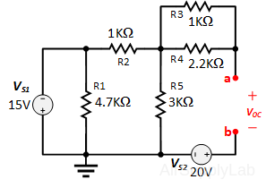
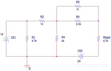
Exp #1: The Theoretical Thévenin Equivalent Circuit
Part 1A – Method-1: Thévenin Resistance with Deactivated Sources
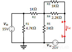
- Remove the load resistor at the terminal points a-b and predict the theoretical Thévenin resistance (RTh)thy-1 with all sources deactivated.
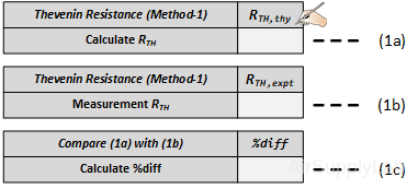
Show your calculations and record the your result in the Table (1a).
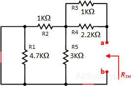
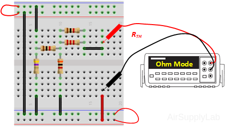
- Deactivate all the sources in the circuit and measure the experimental Thévenin resistance (RTh)expt using a DMM. Measure the RTH and record the value in the Table (1b).

- Compare the predicted (1a) and experimental Thévenin resistances (1b) using a percent difference. How do they compare?
Part 1B – Method-2: Thévenin Resistance using vOC / iSC
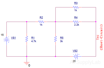
Short-Circuit Current ISC
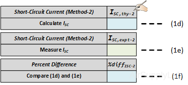
- Remove the load resistor at the terminal points a-b and insert a short. Predict the short circuit current (ISC)thy-2 with all sources activated. Show all work, and record your result in the table (1d).
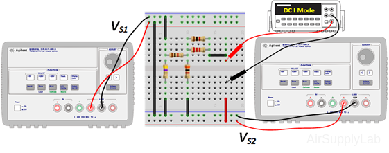
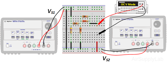
- Energize the circuit and measure the short circuit current (ISC)expt-2. Record your measured value in Table (1e)
- Compare the predicted (1d) and experimental short circuit current (1e) using a percent difference. How do they compare?
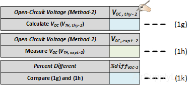
Open-Circuit Voltage VOC
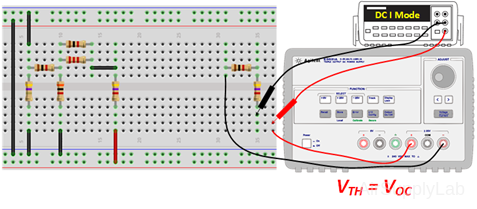
- Remove the short between the terminals points a-b and predict the open circuit voltage (VTh)thy =VOC . Show all work and record your calculated result in the Table (1g).
- Energize the circuit and measure the open circuit voltage (VTh)expt. Record your measured value in Table (1h).
- Compare the predicted (1g) and experimental short circuit current (1h) using a percent difference. How do they compare?
Thévenin Resistance
- Predict the Thévenin resistance using Method-2: (RTh)thy-2 = (VOC)thy-2 /(ISC)thy-2. Record (RTh)thy-2 and record the calculated value in the Table (1m).
Compare the predicted (1m) and measured Thévenin resistance (1b) using the measured Thévenin resistance obtained from Part 1A. How do they compare?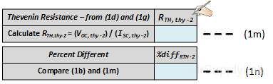
- Compare the Thévenin resistances for both methods (RTh)thy-1 (1a) and (RTh)thy-2 (1m). How do they compare?
Use sentence concise sentences to explain whether both methods are equivalent?
Exp#2: The Experimental Thévenin Equivalent Circuit
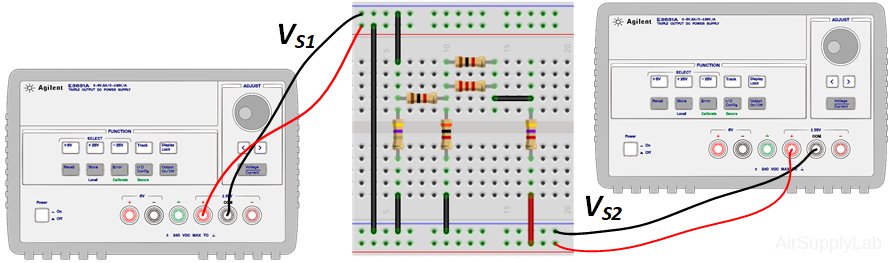
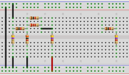
- Do not break down your circuit. Construct a second circuit on the breadboard – the Thévenin equivalent circuit
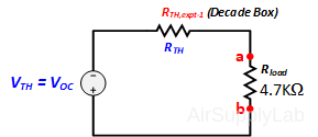
where the Thévenin resistance is the measured value obtained in part 1A (in the Tbale 1b) and the Thévenin voltage is the measured value obtained in part 2B (in the Table 1h).
If you do not have decade box, you can use 1K Ω resistor for RTH. - Measure the current through the load resistor Iload in both the original and the Thévenin equivalent circuits.
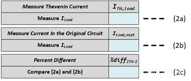
- Measure the Iload in the Thévenin equivalent circuit. Record the result in the Table 2(a).
- Measure the Iload in the original circuit. Record the result in the Table 2(b).
- Measure the Iload in the Thévenin equivalent circuit. Record the result in the Table 2(a).
- Compare load resistor currents for both the original and the Thévenin equivalent circuits using a percent difference (2c). How do they compare?
- Use short concise sentences to explain whether Thévenin’s theorem has been verified?
Exp #3: Maximum Power Transfer (Validating the condition RL = RTh)
- In the original circuit, replace the load resistance with a Decade Resistor box. Note that the Thévenin resistance is the resistance already on your circuit board.
- Measure the voltage across the Decade box as the resistance is changed in increments of 100 Ω and starting at 1 KΩ ending at 2 KΩ. As the Decade resistance approaches the Thévenin resistance, reduce the increments to 50 Ω.
- Set up a data table of Rload, vload, and Pload and plot Pload verse Rload.
- Referring to your plot, what value of Rload resulted in maximum power transfer to the load resistance? How do the theoretical and measured values compare?
Exp #4: The PSpice Thévenin Circuit
- Use PSpice to find the Thévenin voltage VTh and resistance RTh. Use PSpice to find the Thévenin voltage VTh and resistance RTh.
- To simulate the Thévenin voltage VTh, “Capture” a circuit when the load resistance is replaced with a 5 GΩ resistor. The voltage across the load will be the open circuit voltage VOC = VTh.
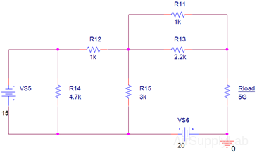
Hint: Place the PSPice Ground at one of the nodes of the load resistance.
To simulate the Thévenin resistance RTh, use the relationship RTh = VOC / ISC. Make a second copy of the above circuit, renumber the parts in the duplicate circuit, and
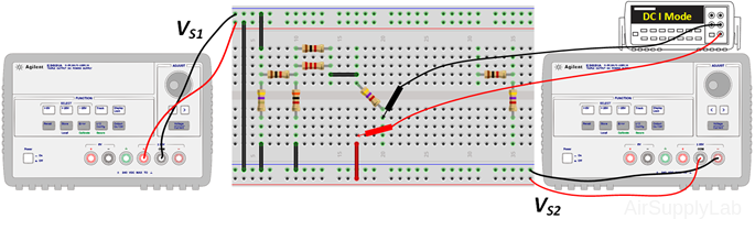
- Replace the load resistance with a short circuit wire. The current through the 20 V source (VS2) will be the short circuit current ISC.
- Simulate both two circuits simultaneously on the same page. Calculate RTh using RTh = VOC / ISC.
- To Simulate the Power for the Thévenin’s circuit do the following:
- Change Rload resistor value to {RL}
- Place a "PARAM" part from "SPECIAL" library into your schematic page.
- Right click on the element PARAM, choose "Edit Properties..." to open "Property Editor" window. Then click "New Property..." button to create a new property and put RL as the property name with any resistor value like 1k. Click ok to close the dialog window.
- Click "Display..." button, and select display format to "Name and Value". After that, close the "Property Editor" window, then go back to "SCHENATIC:PAGE" window.
- Click "Edit Simulation Profile" button, or select from menu PSpice ➤ Edit Simulation Profile.
- Change the Analysis Type to "DC Sweep", select Sweep Variable to Global Parameter and set the Parameter name to RL, set up the rest of the values, such as Start Value, End Value and Increment. Careful: Do set the initial to zero but 1.
- Click "Start Simulation", then check result from the simulation program.
Questions
- Explain why Rload is needed to be replace with a 5 GΩ resistor in the PSpice simulations. Why not just take Rload out of the circuit and simulate the resulting circuit?
- Suppose you have two boxes in front of you. One box contains a Thevenin Equivalent (voltage source in series with a resistor) and the other box contains a Norton Equivalent (current source in parallel with a resistor). Each box has a pair of terminals available for measurement. You cannot open the boxes. You may make any electrical measurements at the terminals. You also have access to the outside surface of the boxes. Can you determine which box contains the Thevenin Equivalent and which box contains the Norton Equivalent? Or is it impossible to determine which circuit is in which box? Justify your answer in detail.