Lab 09: Divider Rules for Voltage and Current
Objectives
- Practice measuring voltages and current in series and parallel circuits.
- Verify the divider rules for voltage and current.
Equipments
Background
Voltage Divider
- In parallel circuits, the voltage across each of the component is always same.
- in series circuits, the voltage drop across a resistor is directly proportional to the resistance of the resistor.
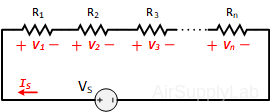
Figure 1: A Parallel Circuit with n Resistors
The Voltage Divider Rule (VDR) states that the voltage across an element or across a series combination of elements in a series circuit is equal to the resistance of the element or series combination of elements divided by the total resistance of the series circuit and multiplied by the total impressed voltage:
\({V_n} = \frac{{{R_n}}}{{{R_{total}}}} \times {V_S}\)
\({R_{total}} = \sum\limits_{i = 1}^n {{R_i}} \)
Current Divider
- In series circuits, the current always remains same through all components.
- In parallel circuits, the current doesn't remains same, instead it divides.
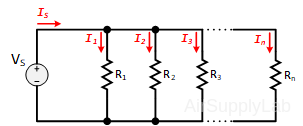 Figure 2: A Parallel Circuit with n Resistors
The Current Divider Rule (CDR) states that the current through one of the parallel branches is equal to the resistance of the other branch divided by the sum of the resistances of the two parallel branches and multiplied by the total current entering the parallel branches. That is:
\({I_n} = \frac{{{R_{parallel}}}}{{{R_n}}} \times {I_{source}}\)
\(\frac{1}{{{R_{parallel}}}} = \sum\limits_{i = 1}^n {\frac{1}{{{R_i}}}} \)
Procedure
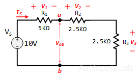
Exp #1: Voltage Divider Rule (VDR)
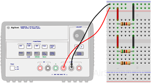
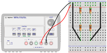
Construct the circuit
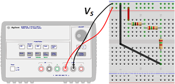
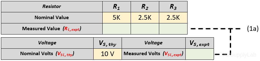
- Measure the actual resistance values and the power supply voltage with a Digital Multimeter (DMM). The display range on the DMM should be chosen so as to obtain the maximum accuracy (i.e. maximum number of digits for the DMM reading). Record your measured values in the table (1a).
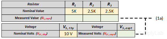
- Without making any calculations, what value would you expect for the voltage across each resistor (Using nominal values)? Explain your reasoning and record your result in the following Table (1b).

- Calculate V1, V2 and V3 using the VDR with the measured values from table (1a). Measure V1, V2 and V3 and determine the percent difference between the theoretical and experimental results for V1. How do they compare? Record your calculations and measured data in the table (1c), (1d) and (1e.1).
- If R2 = R3, then the VDR states the V2 = V3. Measure voltages V2 and V3, and comment on the validity of these statements.
- Using VDR, calculate the voltage Vab. Measure Vab and determine the percent difference (1e.2) between the theoretical (1c) and experimental results (1d). How do they compare?

Data Table 1: Experimental Results for Exp #1
Exp #2: Current Divider Rule (CDR)
Construct the circuit
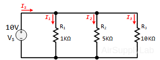
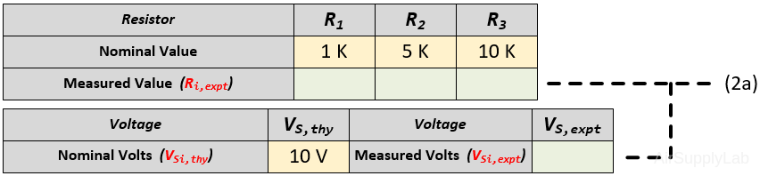
- Measure the actual resistance values and the power supply voltage with a Digital Multimeter (DMM). The display range on the DMM should be chosen so as to obtain the maximum accuracy (i.e. maximum number of digits for the DMM reading). Record your measured values in the table (2a).
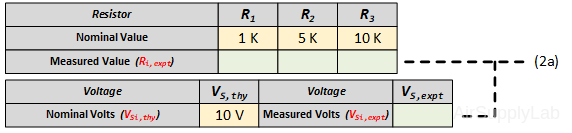
- Without making any calculations, what value would you expect for the current through each of the resistors? Record your results in the table (2b) and explain your reasoning.

- Measure the IS, I1, I2, and I3 with DMM and record the results in the table (2c). Calculate the currents I1, I2, and I3 using the CDR from the measured value of IS and measured resistance values. Record your calculations in the table (2d). Then calculate the percent differences between (2c) and (2d) into the table (2e). Explain the reasoning behind the values of all the currents.
- Based on previous measurements, are your conclusions of Exp #2 verified? Use a percent difference to compare the theoretical (2b) and experimental results (2c).

Data Table 2: Experimental Results for Exp #2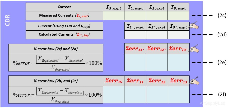
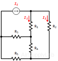
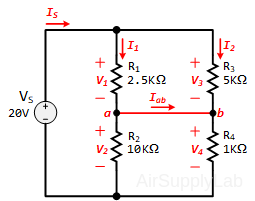
Exp #3: Challenge Circuit
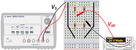
Construct circuit:
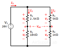
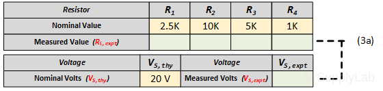
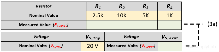
- Measure the resistance for each resistor and power supply voltage using the DMM in DC Voltage Mode (DC V).
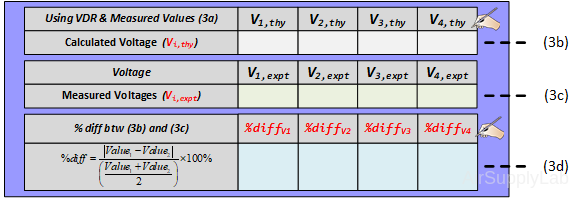
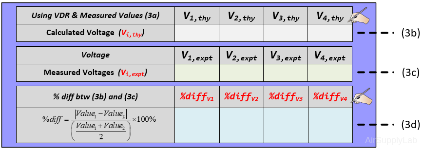
- Calculate the voltages V1, V2, V3 and V4 using the VDR with measured resistor values and voltage from previous table (a). Write your calculation results in the following table (b). Measure the voltages V1, V2, V3 and V4 and record the measured values in the following table (c). Then use a percent difference to compare the calculated and measured results in table (d). How do they compare?
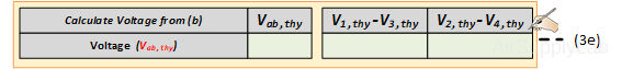
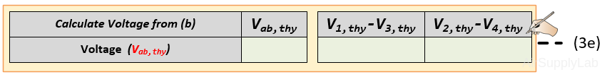
- Using the previous results in the table (3b), calculate the voltage Vab using KVL, then write your calculation results in table (3e).
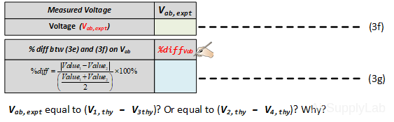
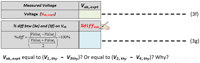
- Measure the voltage Vab using a DMM (DC Voltage mode) and record the value in the table (f). Then use a percent difference to compare the calculated and measured results. How do they compare? Is the voltage Vab,expt equal to V1 – V3? or equal to V2 – V4? Explain your reasoning?
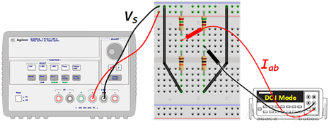
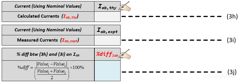
Challenge
Suppose now that a short is placed across the terminal points ab. Calculate the current Iab through the short. Measure the current Iab and use a percent difference to compare the theoretical and experimental results. How do they compare?
Questions
- Can you apply current division to obtain I1 and I2 for the circuit shown in the figure below? Explain briefly.