Lesson 03: Data Types
All variables in Verilog have a predefined type. There are only two families of data types: nets and registers.
- Net variables act like wires in a physical circuit and establish connectivity between design objects that represent hardware units.
- Register variables act like variables in computer programming languages — they store information while the program executes.
Logic Values
Verilog supports four logic values and eight strengths to model the functionality of real hardware. There are two additional unknown logic values (H and L) that may occur internal to the simulation, but which cannot be used for modeling.
| Logic Value | Description |
|---|---|
| 0 | Zero, Low, or False |
| 1 | One, High, or True |
| x or X | Unknown, Don't care, or Uninitialized (either 0 or 1) |
| z or Z | Undefined, High-Impedance, or Floating |
| L | Partially unknown; either 0 or Z, but not 1 (Internal simulation value only) |
| H | Partially unknown; either 1 or Z, but not 0 (Internal simulation value only) |
Strengths
Verilog has 8 strength levels: 4 drivings, 3 capacitive, and high impedance (no strength). The words strenght0 specifies the strength when the net drivers drive the value 0; strength1 specifies the strength when the net drivers drive the value 1. The capacitive strengths are for trireg nets only.
The table below shows the strengths:
| Strength Level | Name | Keyword | Display Mnemonic |
|---|---|---|---|
| 7 | Supply drive | supply0, supply1 | Su0 Su1 |
| 6 | Strong drive | strong0, strong1 | St0 St1 |
| 5 | Pull drive | pull0, pull1 | Pu0 Pu1 |
| 4 | Large capacitive | large | La0 La1 |
| 3 | Weak drive | weak0, weak1 | We0 We1 |
| 2 | Medium capacitive | medium | Me0 Me1 |
| 1 | Small capacitive | small | Sm0 Sm1 |
| 0 | High impedance | highz0, highz1 | HiZ0 HiZ1 |
The default strength is strong drive. For pullup and pulldown gates, the default strength is pull drive; for trireg the default strength is medium capacitive; and for supply nets, the default strength is supply drive.
A net that is not being driven has a high impedance strength, except for tri0 and tri1 that have pull strength; trireg hold their last strength; and supply nets have supply strength.
Data Types
Verilog has two major data type classes:
- Net data types are used to make connections between parts of a design.
- Nets reflect the value and strength level of the drivers of the net or the capacitance of the net and do not have a value of their own.
- Nets have a resolution function, which resolves a final value when there are multiple drivers on the net.
- Variable data types are used as temporary storage of programming data.
- Variables can only be assigned a value from within an initial procedure, an always procedure, a task, or a function.
- Variables can only store logic values; they cannot store logic strength.
- Variables are un-initialized at the start of the simulation and contain a logic x until a value is assigned.
Nets
The net variables represent physical connections between hardware elements. Nets can not store values (except trireg) but can only transmit logic signals. Just as in real circuits, nets have values continuously driven on them by the outputs of devices that they are connected to.
Nets are declared primarily with the keyword wire. Nets are one-bit values by default unless they are declared explicitly as vectors. Nets get the output value of their drivers. If a net has no driver, it gets the value z.
Net data types are wire, tri, wor, trior, wand, triand, tri0, tri1, supply0, supply1, and trireg. wire is the most frequently used type. A net data type must be used when a signal is:
- driven by the output of a module instance or primitive instance.
- Connected to an input, or inout port of module in which it is declared.
- On the left-hand side of a continuous assignment.
| Net Type | Description | Supported Logical Values | Default Value | Default Strength |
|---|---|---|---|---|
| wire | Interconnecting wire | 0, 1 | z | |
| wor | Wired outputs OR together, emitter-coupled logic | 0, 1 | z | |
| wand | Wired outputs AND together; open-collector resolution | 0, 1 | z | |
| supply0 | Constant logic 0 (supply strength) | 0 | 0 | supply |
| supply1 | Constant logic 1 (supply strength) | 1 | 1 | supply |
| tri0 | Pulls down when tri-stated | 0, 1 | 0 | pull |
| tri1 | Pulls up when tri-stated | 0, 1 | 1 | pull |
| tri | Same as wire, but it will be three-stated in hardware | 0, 1, z | z | |
| trior | Same as wor. The physical net is to be three-stated. | 0, 1, z | z | |
| triand | Same as wand. The physical net is to be three-stated. | 0, 1, z | z | |
| trireg | Holds last value when tri-stated (capacitance strength) | 0, 1 | x | medium |
tri
module mux(a, b, out, control);
input   a, b, control;
output  out;

tri     out;

bufif0 B1(out, a, control);     // drives a when control = 0; z otherwise
bufif1 B2(out, b, control);     // drives b when control = 1; z otherwise
trireg
trireg variable is used to model nets having a capacitance that stores values.
tri0 and tri1
tri0 and tri1 are used to model resistive pulldown and pullup devices.
- A tri0 net has a value of 0 if nothing is driving the net.
- Similarly, tri1 net has a value of 1 if nothing is driving the net.
supply0 and supply1
supply0 and supply1 define wires tied to logic 0 (ground) and logic 1 (power) respectively.
- supply1 is used to model a power supply.
- supply0 is used to model ground.
Nets declared as supply1 or supply0 have constant logic value.
supply1     vcc;        // All nets connected to vcc are connected to power supply
supply0     gnd;        // All nets connected to gnd are connected to ground
wor, wand, trior, and triand
Variables (Registers)
Variables represent data storage elements. Variables retain value until another value is placed onto them. Unlike a net, a variable does not need a driver. Verilog variables do not need a clock as hardware registers do. Values of variables can be changed anytime in a simulation by assigning a new value to the variable.
Variable data types are used for programming storage in procedural blocks.
- Variables store logic values only, and they do not store logic strength.
- A variable data type must be used when the signal is on the left-hand side of a procedural assignment with an always or initial block.
- Variables were called "registers" in older versions of the Verilog standard.
| Variable Type | Description | Default Value |
|---|---|---|
| reg | a variable of any bit size; unsigned unless explicitly declared as signed. | x |
| integer | a signed 32-bit variable | 0 |
| time | an unsigned 64-bit variable | 0 |
| real | a double-precision floating-point variable | 0.0 |
| realtime | same as real | 0.0 |
In the simulation, a variable can set an initial value, which is set in simulation time 0.
reg a, b, c;                        // three scalar (1-bit) variables
reg signed [7:0] d1, d2;            // two 8-bit signed variables
reg        [7:0] mem [0:3][0:15];   // a 2-dimensional array of 8-bit variables

integer i, j;                       // two 32-bit signed integer variables
real    r1, r2;                     // two double-precision variables
reg     clk = 0, reset = 1;         // two reg variables with initial values
reg
The data type reg is an abstraction of a hardware storage element, but it does not correspond directly to physical memory.
- A reg variable has a default initial value of x.
- The default size of a register variable is a single bit.
- Verilog operators create a reg variable as an unsigned value.
- reg does not mean register, It can be modeled as a wire or a storage cell depending on context.
- When used in combinational expressions in an always block, no storage is implemented.
- When used in sequential statements (begin/end, if, for, case, etc.), then a latch or flip-flop will be created.
A register variable may be assigned value only by a procedural statement, a user-defined sequential primitive, a task, or a function.
Negative Numbers
reg        [7:0] a;
reg signed [7:0] b;
reg        [7:0] c;
reg signed [7:0] d;

initial begin
  a =  -8'd69 ;
  b =  -8'd69 ;
  c =  -8'd69 ;
  d =  -8'd69 ;
  #10;
  $display("a      : %8b, %d", a, a);
  $display("b      : %8b, %d", b, b);
  a = a/2     ;
  b = b/2     ;
  #10;
  $display("a=a/2  : %8b, %d", a, a);
  $display("b=b/2  : %8b, %d", b, b);
  $display("c >>>1 : %8b, %d", c>>>1, c>>>1);
  $display("d >>>1 : %8b, %d", d>>>1, d>>>1);
end
Results:
a : 10111011, 187
b : 10111011, -69
a=a/2 : 01011101, 93
b=b/2 : 11011110, -34
c >>>1 : 01011101, 93
d >>>1 : 11011101, -35
integer
The data type integer supports numeric computations in procedural statements. An integer is a general-purpose register data type used for manipulating quantities. Although it is possible to use reg as a general-purpose variable, it is more convenient to declare an integer variable for purposes such as counting.
- For synthesis, it is mainly used as loop indexes, parameters, and constants.
- The default width for an integer is the host-machine word size, which is implementation-specific but is at least 32-bits.
- An integer variable has a default initial value of 0.
- The integers store values as signed quantities. A negative integer is stored in 2's complement format.
- The number assigned to an integer variable must have a decimal equivalent (i.e., x and z are not allowed)
integer counter;                // general purpose variable used as a counter
integer arrayOfInts [1:100];    // integer array

initial
    counter = -1;               // A negative one is stored in the counter
Negative Numbers
An integer will be interpreted as a signed value in 2's complement form if it is assigned a value without a base specifier (e.g., A = -24). If the value assigned has a specified base, the integer is interpreted as an unsigned value.
integer A;

initial begin
    A = -12;
    $display("A  : %d %h", A, A);
    A = -32'd12;
    $display("A  : %d %h", A, A);
    A = -12 / 4;
    $display("A  : %d %h", A, A);
    A = -32'd12/4;
    $display("A  : %d %h", A, A);
end
Results:
A : -12 fffffff4
A : -12 fffffff4
A : -3 fffffffd
A : 1073741821 3ffffffd
time
The data type time supports time-related computations within procedural code in Verilog models.
- time variables are stored as unsigned 64-bit quantities, which can be used in conjunction with the $time system task to hold simulation time.
- Time is not supported for synthesis and hence is used only for simulation purposes.
- A time variable has a default value of 0.
Verilog simulation is done with respect to simulation time. time variables can be used to store the simulation time. The system function $time is invoked to get the current simulation time.
time    sim_time1;      // Define a time variable sim_time1

sim_time1 = $time;      // Save the current simulation time
Simulation time is measured in terms of simulation seconds. The unit is denied by s, the same as real-time.
real
Variables having type real are stored in double precision, typically a 64-bit value. An object of type real may not be connected to a part of a module or a terminal of a primitive.
- A real variable has a default initial value of 0.0.
- real variables can be specified in decimal notation (e.g., 3.14) or in exponential notation. (e.g., 3e6, which is 3×10⁶)
- When a real value is assigned to an integer, the real number is rounded off to the nearest integer.
real    delta;          // Define a real variable called delta
real    pi;             // Define a real variable called pi

initial begin
    delta = 4e10;       // delta is assigned in exponential notation
    pi    = 3.1415;     // pi is assigned a value 3.1415
end

integer i;              // Define an integer i

initial begin
    i = pi;             // i gets the value 3 (rounded value of 3.1415)
end
realtime
Variables having type realtime are stored in real number format.
- A realtime variable has a default value of 0.0.
Constant Values
Prarmeters
Prarmeters
Verilog allows constants to be defined in a module by the keyword parameter. Parameters cannot be used as variables. Parameter values for each module instance can be overridden individually at compile time. Parameters value can be changed at module instantiation or by using the defparam statement.
Parameters allow constants like word length to be defined symbolically in one place. This makes it easy to change the word length later across the entire design by changing only the parameter. It is used in a fashion similar to what you use #define for in C when you are programming in C.
- Parameters represent constants that need to be used in many places in the design.
- Parameters do not belong to either the register or the net group.
- Parameters are not variables.
parameter   PORT_ID = 5;                // Define a constant PORT_ID
parameter   CACHE_LINE_WIDTH  = 256;    // Constant defines width of cache line
parameter   signed [15:0] WIDTH;        // Fixed sign and range for parameter WIDTH
Mult-Bit MUX
Assume we wanted to create the following circuit:
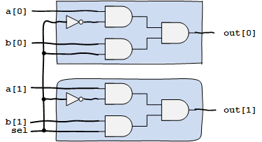
There have two input muxes together and they are in parallel.
module bus_mux(a, b, sel, out);
    parameter   N = 2;
    input  [N-1:0] a;
    input  [N-1:0] b;
    input  sel;
    output out;
    wire [N-1:0] sel_bus;

    assign sel_bus = {N{sel}};              // replicates 2 times
    assign out = (~sel_bus & a) | (sel_bus & b);

endmodule
Local Parameters
Verilog HDL local parameters (defined using keyword localparam) are identical to parameters except that they cannot be directly modified with the defparam statement or by the ordered or named parameter value assignment. The localparam keyword is used to define parameters when their values should not be changed. This provides protection against inadvertent parameter redefinition.
Example: State Machine Name
The state encoding for a state machine can be defined using localparam. The state encoding cannot be changed.
localparam  S_IDLE  = 4'b0001,
            S_1     = 4'b0010,
            S_2     = 4'b0100,
            S_3     = 4'b1000;
Strings
A string is a sequence of characters that are enclosed by double quotes ("). Verilog does not have a distinct data type for strings. Instead, a string must be stored within a properly sized register variable by a procedural assignment statement. The width of the register variables must be large enough to hold the string. Each character in the string takes up 8-bits (1 byte). If the width of the register is greater than the size of the string, Verilog fills bits to the left of the string with zeros.
The restriction on a string is that it must be contained on a single line, that is, without a carriage return. It cannot be on multiple lines. Strings are treated as a sequence of one-byte ASCII values.
"Welcome to FPGA World" // is a string
"a / b" // is a string
Strings can contain special characters:
| Character | Meaning |
|---|---|
| \n | Newline character |
| \t | Tab character |
| \\ | Backslash (\) character |
| \" | Double quite (") character |
| \ddd | A character specified by the octal digit |
| %% | Percent (%) character |
reg [12*8:1]    str1, str2;

str1 = "EE4480";
str2 = "Verilog";
- The Left Hand Side (LHS) of procedural assignments must be of a Register type.
- For continuous assignments outside of procedural blocks, LHS must be Nets (wires)