Lesson 06: Modules and Ports
Verilog describes a digital system as a set of modules. A module is the main building block in Verilog, which contains the statements specifying the circuit, and it can be compared to functions() in C language. Modules can be embedded within other modules, and a higher-level module can connect with its lower-level modules using their input and output ports.
6.1 Ports
Ports are a set of signals that are used as inputs and outputs to other modules and are the primary way of communicating with them.
There are three types of ports:
| Port | Default Data Type | Description | Can be Redeclared as |
|---|---|---|---|
| input | wire | Receive signal from the outside module, and can only be read from. | Nets |
| output | wire | Send signals to the outside module that can be read or written to. | Nets or Registers |
| inout | wire | For tri-state signals only. It can send and receive signals and be read from or written to. | Nets |
In Verilog, all ports are by default considered as nets of type wire. Ports of the type input and inout cannot be declared as reg.
However, if output ports hold their value, they must be declared as reg.
Port Declaration
- Input Ports
input port_name;
input [width-1:0] port_name; // for multi-bit input - Output Ports
output port_name;
output[width-1:0] port_name; // for multi-bit input - Bidirectional Ports
inout port_name;
inout [width-1:0] port_name; // for multi-bit input
6.2 Modules
A module in Verilog defines a block of hardware. It can contain instances of other modules, continuous assignments, procedural blocks, and other constructs.
A typical Verilog segment is given below:
module <module name> (<port list>);
<port declarations>
<module declarations>
<module items>
endmodule
In Verilog, a module is declared by the keyword module and a corresponding keyword endmodule must appear at the end of the module definition. Each module must have a unique module name, which is the identifier for the module, and a port list, which describes the input and output terminals of the module. An entire circuit can be described in a module.
Module Name
module name
The module name identifies a module uniquely. This means that a name or an identifier is assigned to a module to identify it.
Examples of Module Names
The following are some examples of valid and invalid module names:
module mux4to1(<port list>); // Valid
module mux_4to1(<port list>); // Valid
module _4to1_mux(<port list>); // Valid
module 4to1mux(<port list>); // Invalid, the first character cannot be a number
module $4to1mux(<port list>); // Invalid, can not have $ sign
Port List and Declarations
Port list
The port list of a module is the interface between the module and its environment. The port list is enclosed in parentheses, and commas are used to separate list elements. The statement is terminated with a semicolon (;)
port declarations
All the ports in the port list need to be declared as input, output, or input (for bidirectional signals). The direction of the port can be specified in either the port list or the port declarations, but cannot be both.
Declare the direction of ports in the port declaration (Verilog-1995)
module mux4to1( in0, in1, in2, in3, sel, out);
input in0, in1, in2, in3;
input [1:0] sel;
output out;
endmodule
Declare the direction of the ports inside the port list (Verilog-2001, 2005)
module mux4to1( input in0, input in1, input in2, input in3, input sel[1:0], output out);
// No port declarations are needed
endmodule
module mux2to1( input in0, in1, sel, output out);
// No port declarations are needed
endmodule
Verilog File
The first step to design a digital circuit using Verilog is to draw a module diagram, as shown below. In the module diagram, the following items must be declared:
- Name of module
- Type of its connections (input, output, or bidirectional signal)
- Names of each port
Then, write the Verilog code for the module. Usually, a Verilog source file contains only one module, and the module name should match the Verilog source file name.
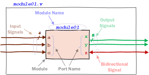
Figure 1: Draw a Module Diagram
module01.v
module module01 (a, b, c, x, y, z);
input [3:0] a;
input b;
input c;
output [7:0] x;
output y;
inout z;
endmodule
However, multiple modules can reside in a Verilog file, but external modules can connect to a module matching the Verilog file name, and other modules can only be connected inside the Verilog file, so this is not recommended.
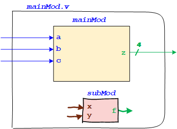
Figure 2: Multiple Modules in one Verilog File
mainMod.v
module mainMod (a, b, c, z);
input a, b, c;
output [3:0] z;
endmodule
module subMod(x, y,z):
input x, y;
output z;
endmodule
Instantiation of Instances
In Verilog, instantiating instances allows you to include one module within another. This is a key feature for building hierarchical designs, where complex systems comprise simpler submodules.
Steps for Instantiation of Instances
- Define the Module: First, you must define the module you want to instantiate. This module can have inputs, outputs, and internal logic.
- Declare the Ports: When instantiating a module, connect its ports to signals in the parent module.
- Instantiate the Module: Create an instance of the module in the parent module, connecting its ports to the parent module's signals.
Let’s walk through a detailed example step-by-step.
Step 1: Define the Submodule
Define a simple submodule that performs a basic operation, such as an AND gate.
module and_gate (a, b, y);
input a, b;
output y;

assign y = a & b;

endmodule
Step 2: Define the Top Module and Declare Ports
Define the top-level module that will instantiate the and_gate module.
module top_module (a, b, c, y1, y2);
input a, b, c;
output y1, y2;

// Internal signals
wire and_output;
// Instantiate the and_gate module
and_gate U1 (
    .a(a),
    .b(b),
    .y(and_output)
  );

// Additional logic in the top module
assign y1 = and_output;
assign y2 = and_output & c;

endmodule
Detailed Explanation
- Module Definition: The and_gate module is defined with inputs a and b and output y.
- Top Module Definition: The top_module has inputs a, b, and c and outputs y1 and y2.
- Internal Signals: The top_module declares an internal wire and_output to connect the output of the and_gate to other design parts.
- Instantiation: The and_gate is instantiated within the top_module using the following syntax:
and_gate U1 (
  .a(a),
  .b(b),
  .y(and_output)
);
Here, U1 is the instance name. The ports of the and_gate are connected to signals in the top_module using named port connections. - Additional Logic: The top_module then uses the and_output signal in additional logic, demonstrating how the instantiated module interacts with other design parts.
Top-Level Module
The top-level module in Verilog HDL is the highest in the hierarchy of your design. It is akin to the main() function in C in that both serve as the entry points for their respective designs. It typically instantiates other submodules and connects them.
For example, design modules are normally instantiated within top-level testbench modules, so simulation can be run by providing input stimulus. However, the testbench is not instantiated within any other module because it is a block that encapsulates everything else and, hence, is the top-level module.
6.3 Port Connections
Port connections in Verilog HDL are crucial for defining how modules communicate with each other. When instantiating a module, you need to connect its ports to signals in the parent module. In Verilog, there are two ways of specifying connections among ports of instances:
- Positional Port Mapping
- Named Port Mapping
Positional Port Mapping
In positional port mapping, ports are connected based on their position in the port list. The instance's connection order must match the module definition's port declaration order.
Example:
Assume we have a module and_gate defined as follows:
module and_gate (a, b, y);
input  a, b;
output y;

assign y = a & b;
endmodule
Upper-Level Module with Positional Port Mapping:
module upper_module (in1, in2, out);
input  in1, in2;
output out;

 // Instantiate the and_gate module using positional mapping
and_gate u1 (in1, in2, out);

endmodule
In this example:
- The first port in1 connects to a.
- The second port in2 connects to b.
- The third port out connects to y.
This is inconvenient because the port listed order might change if a new port is added to the list or when the number of ports in the design is very large.
Named Port Mapping
In named port mapping, ports are explicitly connected by name. This method is more readable and less error-prone, especially for modules with many ports.
Example:
Using the same and_gate module:
Upper-Level Module with Named Port Mapping:
module upper_module (in1, in2, out);
input  in1, in2;
output out;

// Instantiate the and_gate module using named mapping
and_gate U1 (
    .a(in1),
    .b(in2),
    .y(out)
);

endmodule
In this example:
- in1 is explicitly connected to a.
- in2 is explicitly connected to b.
- out is explicitly connected to y.
Unconnected/Floating Ports
In Verilog HDL, unconnected or floating ports refer to input or output ports intentionally left unconnected during module instantiation. These ports do not connect to any internal signal or external pin. Handling unconnected ports properly ensures the design works as expected and does not generate unintended behavior or synthesis warnings/errors.
Handling Unconnected Ports:
- Input Ports: If an input port is left unconnected, it is generally safe but might assume an undefined logic level. To avoid this, connect it to a defined logic level (e.g., 1'b0 or 1'b1) or leave it unconnected if your design tolerates floating inputs.
- Output Ports: Unconnected output ports do not affect the internal logic of the module, but they can lead to synthesis warnings. To avoid these warnings, you can explicitly connect them to an unused signal or leave them unconnected if your toolchain supports it.
- Inout Ports: Leaving inout ports unconnected can result in floating nets, which might cause issues in simulation and synthesis. You should handle inout ports carefully, typically connecting them to an appropriate signal or driving them to high impedance (z).
Positional Port Mapping
In positional port mapping, ports are connected based on their order in the module definition. If you want to leave a port unconnected, you can leave a blank position or use a placeholder.
Example: Positional Port Mapping with Unconnected Ports
// Instantiate and_gate with the second input port (b) unconnected
  and_gate U1 (
    a,  // Connected to input 'a'
    ,   // Leave 'b' unconnected
    y   // Connected to output 'y'
  );
Named Port Mapping
In named port mapping, ports are explicitly connected by name, making it easier to leave specific ports unconnected.
Example: Named Port Mapping with Unconnected Ports
// Instantiate and_gate with the second input port (b) unconnected
  and_gate U1 (
    .a(a),  // Connected to input 'a'
    .b(),   // Leave 'b' unconnected
    .y(y)   // Connected to output 'y'
  );
Summary
- Positional Port Mapping:
- Ports are connected based on their order in the module definition.
- It is concise but less readable and more error-prone.
- Unconnected ports can be left blank or with a placeholder.
- Named Port Mapping:
- Ports are explicitly connected by name.
- It is more readable and less error-prone, especially for modules with many ports.
- Unconnected ports are indicated by leaving them empty.