Tiva Lab 13: DTMF Tones Generator / MIDI Player
Objective
- Produce simply tones by square wave signal
- Using PWM to generate different frequencies of square wave
Required Reading Material
- Lesson 13: Pulse-Width Modulation (PWM)
- EE3450-Tiva Lab 05: Scan a Key from a Matrix Keypad
- Lesson 08: Add ezTiva Library into Your Project
- Buzzer
Background Information
In this lab, the system will generate DTMF tones to dial the numbers pressed on the keypad. The DTMF tone is driven by a square wave that is generated by the Pulse Width Modulation (PWM) module of the Tiva TM4C microcontroller instead of Digital-to-Analog Converters (DACs). Since each PWM generator can only produce one square signal, to generate dual tones, the system needs two PWM generators to produce two tones at different frequencies.
Calculation
The PWM generator can produce a square wave signal. The PWM LOAD register controls the frequency of the signal. Changing the value in the LOAD register will change the frequency of the PWM signal (square wave). The formula for the LOAD value in different PWM frequencies is shown below:
\(LOAD = \frac{{{f_{PWMTimer}}}}{{{f_{PWM}}}} = \frac{{({f_{SysClk}}/PWMDIV)}}{{{f_{PWM}}}}\)
- Configure the system clock frequency to 40 MHz by using ezTiva LIB API (check here).
- Configure two PWMs by calling Setup_PWM() function.
- Configure GPIOs by calling Setup_GPIO() function.
- Create a function: char ReadKeypad() to read the keypad and then return the ASCII code for the key pressed by the user.
- Create a function: PlayDTMF(digit, duration) to generate dial tones.
- The digit is a character to represent the dial ton key for '0' ~ '9', 'A' ~ 'D' and '*', '#'.
- Calculate the LOAD value for each ton frequency.
- The duration is the period of the tone in ms.
- In the infinite for-loop:
- Call ReadKeypad() to detect the key pressed by the user. (Use the code you implemented in Lab 5, Exp #2.)
- The call PlayDTMF() function generates a dial tone if any key is pressed.
Required Components List
| 220-ohm Resistor | × 2 | |
 |
4x4 Matrix Keypad | × 1 |
| Passive Buzzer | × 1 | |
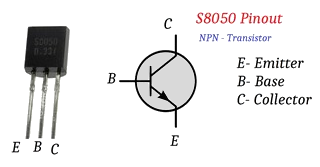
| S8050 NPN Transistor | × 1 |
Circuit Diagram
You have to decide which two PWM signals will be used to generate the DTMF tone and then connect both PWM signals to an NPN S8050 transistor with two 220 ohm resistors to drive the passive buzzer as shown as above figure. A matrix keypad is also connected to the Tiva LaunchPad board.

Pin configurations:
| Device | Port.Pin | Signal Type | PCTL | Direction | Drive Mode |
|---|---|---|---|---|---|
Procedures
- Create a new folder under the EE3450 folder and name it Lab13_DTMF_MIDI. Then double-click the folder you just created to jump into it.
- Launch the Keil μVisio and create a new project, save the project as Lab13_DTMF_MIDI.
- Add the Common and ezTivaLIB folders to the include paths under the "Options for Target" setting.
- Add ezTiva LIB into your project, and increase the stack and heap size under the "startup_TM4cXXX.s (Startup)" setting.
Configurations
PWM Initialization and Configuration
PWM Initialization & Configuration
Find the frequency of the system clock, and calculate the frequency of the PWM Timer.
| System Clock SysClk (Hz) |
PWMDIV | fPWMTimer = SysClk / PWMDIV (Hz) |
Check the PCTL table (for 123G or 1294) to find the pins which support PWM peripheral signal
| GPIO Port.Pin |
PWM Module |
PCTL | PWM | |||||||
| Module (m) |
Generator (n) |
Signal GEN | Output | Signal Type | Output Frequency fPWM |
LOAD Value (16-bit) |
Initial CMP Value (16-bit) |
|||
You have to know the frequency of the System Clock (1), the frequency of PWM output signal (2), and the initial value for duty cycle (3). Then, calculate the LOAD value and CMP value.
\(LOA{D_{16bit}} = \frac{{{f_{PWMTimer}}}}{{{f_{PWM}}}}\)
For Left-Aligned PWM Signals
Calculate CMP value by duty cycle (%):
\(CM{P_{16bit}} = LOAD \times (1 - Dut{y_\% }) = \frac{{{f_{PWMTimer}}}}{{{f_{PWM}}}} \times (1 - Dut{y_\% })\)
Calculate CMP value by pulse width:
\(CM{P_{16bit}} = LOAD - \frac{{{T_{PulseWidth}}}}{{{T_{PWMTimer}}}} = ({T_{PWM}} - {T_{PulseWidth}}) \times {f_{PWMTimer}}\)
For Right-Aligned PWM Signals
Calculate CMP value by duty cycle (%):
\(CM{P_{16bit}} = LOAD \times Dut{y_\% } = \frac{{{f_{PWMTimer}}}}{{{f_{PWM}}}} \times Dut{y_\% }\)
Calculate CMP value by pulse width:
\(CM{P_{16bit}} = \frac{{{T_{PulseWidth}}}}{{{T_{PWMTimer}}}} = {T_{PulseWidth}} \times {f_{PWMTimer}}\)
The following steps show how to initialize PWM peripheral.
- Enable Clock to the PWM Modules (RCGCPWM register)
TM4C123G:
SYSCTL->RCGCPWM = MyDefines.h8 4 2 1 8 4 2 1 7 6 5 4 3 2 1 0 bit PWM
Module 1PWM
Module 0PWM 0 0 0 0 - 0 0
= binary = hex
TM4C1294:
SYSCTL->RCGCPWM = MyDefines.h8 4 2 1 8 4 2 1 7 6 5 4 3 2 1 0 bit PWM
Module 0PWM 0 0 0 0 - 0 0 0
= binary = hex
After enable clock signal, check the PRPWM register until the corresponding bit set to 1.
In C:
while ( (SYSCTL->PRPWM & (__) ) != (____ )) {}; - Enable and Setup Clock Divider for all PWM modules
USEPWMDIV: Enable PWM Clock Divisor
- 0: The system clock is the source for the PWM clock
- 1: The PWM clock divider is the source for the PWM clock
PWMDIV: PWM Unit Cloxk Divisor
- 0x0: /2
- 0x1: /4
- 0x2: /8
- 0x3: /16
- 0x4: /32
- 0x5: /64
TM4C123G:
SYSCTL->RCC &= ~(0x7 << 17); // RCC[19:17]=000 PWMDIVRCC 31 ~ 21 20 19 ~ 17 16 ~ 0 bit USEPWMDIV PWMDIV x x
SYSCTL->RCC |=
|= |=
TM4C1294:
PWM0->CC &= ~(0x7); // PWMCC[2:0]=000 PWMDIVPWMCC 31 ~ 9 8 7 ~ 3 2 ~ 0 bit USEPWMDIV PWMDIV x x
PWM0->CC |=
|= |= - PWM Signal Generation Control Register (PWMnCTL)
MODE: Counter Mode
- 0: Count-Down mode
- 1: Count-Up/Down mode
ENABLE: PWM Block Enable
- 0: The entire PWM generation block is disable and not not clocked
- 1: The PWM generation block is enabled and produces PWM signals
PWMnCTL 31 ~ 19 18 17 16 15 ~ 14 13 ~ 12 11 ~ 10 9 ~ 8 bit LATCH MINFLTPER FLTSRC DBFALLUPD DBRISEUPD DBCTLUPD GENBUPD x PWMnCTL 7 ~ 6 5 4 3 2 1 0 bit GENAUPD CMPBUPD CMPAUPD LOADUPD DEBUG MODE ENABLE PWM ->_ _CTL =
= = - Setup the Period of the PWM Signal (PWMnLOAD)
The 16-bit LOAD value is used to control the PWM period.
PWMnLOAD 31 ~ 16 15 ~ 0 bit LOAD PWM ->_ _LOAD =
- Setup the Initial Duty Cycle (PWMnCMPA / PWMnCMPB)
The PWMnCMPA / PWMnCMPB registers are used to compare against the PWM counter. When this value matches the counter, a pulse is output which can be configured to drive the pwmA and pwmB signals (via the PWMnGENA and PWMnGENB).
PWMnCMPA 31 ~ 16 15 ~ 0 bit CMPA PWM ->_ _CMPA =
PWMnCMPB 31 ~ 16 15 ~ 0 bit CMPB PWM ->_ _CMPB =
- Setup PWM Signal Type (PWMnGENA / PWMnGENB)
These register control the generation of the pwmA/pwmB signal based on the load and zero output pulses from the counter, as well as the compare A (CMPA) and compare B (CMPB) pulses from the comparators.
- 0x0: Do nothing
- 0x1: Invert PWM signal
- 0x2: Drive PWM signal Low
- 0x3: Drive PWM signal High
ACTCMPBD: Action for Comparator B in count-down mode
ACTCMPBU: Action for Comparator B in count-up mode
ACTCMPAD: Action for Comparator A in count-down mode
ACTCMPAU: Action for Comparator A in count-up mode
ACTLOAD: Action for Counter = LOAD
ACTZERO: Action for Counter = 0
Counter running in Count-Down mode
PWMnGENA/B 31 ~ 12 11 ~ 10 9 ~ 8 7 ~ 6 5 ~ 4 3 ~ 2 0 ~ 1 bit ACTCMPBD ACTCMPBU ACTCMPAD ACTCMPAU ACTLOAD ATZERO x PWM ->_ _GENA =
= =PWM ->_ _GENB =
= =
Counter running in Count-Up/Down mode
PWMnGENA/B 31 ~ 12 11 ~ 10 9 ~ 8 7 ~ 6 5 ~ 4 3 ~ 2 0 ~ 1 bit ACTCMPBD ACTCMPBU ACTCMPAD ACTCMPAU ACTLOAD ATZERO PWM ->_ _GENA =
= =PWM ->_ _GENB =
= = - PWM Output Enable (PWMnENABLE)
This register provides a master control of which PWM signals are output to the GPIO pins. By disabling a PWM output, the PWM generation process can continue without driving PWM signals to the pins.
- 0: The PWM signal has a zero value
- 1: The generated PWM signal is passed to the GPIO pin
8 4 2 1 8 4 2 1 7 6 5 4 3 2 1 0 bit PWM Module PWM
7PWM
6PWM
5PWM
4- PWM
3PWM
2PWM
1PWM
0pin Value in Hex Register Value to Register - - = ➤ PWM ->ENABLE - - = ➤ PWM ->ENABLE
GPIO Initialization and Configuration
GPIO Initialization Configuration
Next, we need to configure all the GPIO ports and pins that are used in the design.
According to the pin connections, complete the following GPIO configurations for each port. Fills the pin field by the value below:
- 0: Clean the bit
- 1: Set the bit
- x: Do not change the bit
- d: Do not care
For both TM4C123GXL and TM4C1294XL LaunchPads, the Port C [3:0] are used for JTAG/SWD. Therefore, when you configure Port C, you have to use bitwise operators to make sure your new configuration settings do not affect the JTAG/SWD function (PC3 ~ PC0).
Most of GPIO pins are configured as GPIOs and tri-stated by default (GPIOPCTL = 0, CPIOAFSEL = 0, GPIODIR = 0, GPIOPUR = 0, GPIOPDR = 0, GPIOODR = 0)
- Enable Clock to the GPIO Modules (RCGCGPIO register)
TM4C123G: SYSCTL->RCGCGPIO |= (_PORTs); |= binary = hex
8 4 2 1 8 4 2 1 7 6 5 4 3 2 1 0 bit Port F Port E Port D Port C Port B Port A port 0 0 -
TM4C1294: SYSCTL->RCGCGPIO |= (_PORTs); |= binary = hex
After enabling the clock signal, check the PRGPIO register until the corresponding bit is set to 1.8 4 2 1 8 4 2 1 8 4 2 1 8 4 2 1 15 14 13 12 11 10 9 8 7 6 5 4 3 2 1 0 bit Port Q Port P Port N Port M Port L Port K Port J Port H Port G Port F Port E Port D Port C Port B Port A port 0 - - -
In Assembly:
            LDR     R0, =SYSCTL_PRGPIO_R
Wait4GPIO   LDR     R1, [R0]
            TST     R1, #(__)
            BEQ     Wait4GPIO
In c:
while ( (SYSCTL->PRGPIO & ____ ) != ____ ) {}; - Unlock Port
TM4C123G: PD7 and PF0 are locked after reset.
TM4C1294: PD7 and PE7 are locked after reset
If those pins are used in the design, they must be unlocked first. To unlock the port, 0x4C4F434B must be written into the GPIOLOCK register and uncommit it by setting the GPIOCR register.
8 4 2 1 8 4 2 1 7 6 5 4 3 2 1 0 bit Port Pin 7 Pin 6 Pin 5 Pin 4 - Pin 3 Pin 2 Pin 1 Pin 0 pin Value in Hex Register Value to Register - - = ➤ GPIO ->LOCK = 0x4C4F434B - - = ➤ GPIO ->CR - - = ➤ GPIO ->LOCK = 0x4C4F434B - - = ➤ GPIO ->CR
Convert above configuration into registers
- GPIO Analog Mode Select
If any pin is used as an Analog signal (check Signal Type field on table 1), the appropriate bit in AMSEL must be set.
- 0: Digital signal
- 1: Analog signal
8 4 2 1 8 4 2 1 7 6 5 4 3 2 1 0 bit Port Pin 7 Pin 6 Pin 5 Pin 4 - Pin 3 Pin 2 Pin 1 Pin 0 pin Value in Hex Register Value to Register - - = ➤ GPIO ->AMSEL - - = ➤ GPIO ->AMSEL - - = ➤ GPIO ->AMSEL - - = ➤ GPIO ->AMSEL - - = ➤ GPIO ->AMSEL - - = ➤ GPIO ->AMSEL - - = ➤ GPIO ->AMSEL - GPIO Port Control (PCTL)
The PCTL register is used to select the specific peripheral signal for each GPIO pin when using the alternate function mode.
- 0: GPIO
- 1~0xF: Check the GPIO Pins and Alternate Function table
8421 8421 8421 8421 8421 8421 8421 8421 31~28 27~24 23~20 19~16 15~12 11~8 7~4 3~0 bit Port Pin 7 Pin 6 Pin 5 Pin 4 - Pin 3 Pin 2 Pin 1 Pin 0 pin Value in Hex Register Value to Register - - = ➤ GPIO ->PCTL - - = ➤ GPIO ->PCTL - - = ➤ GPIO ->PCTL - - = ➤ GPIO ->PCTL - - = ➤ GPIO ->PCTL - - = ➤ GPIO ->PCTL - - = ➤ GPIO ->PCTL - GPIO Alternate Function Select (AFSEL)
Setting a bit in the AFSEL register configures the corresponding GPIO pin to be controlled by PCTL peripheral function.
- 0: General I/O
- 1: Pin connected to the digital function defined in the PCTL register
8 4 2 1 8 4 2 1 7 6 5 4 3 2 1 0 bit Port Pin 7 Pin 6 Pin 5 Pin 4 - Pin 3 Pin 2 Pin 1 Pin 0 pin Value in Hex Register Value to Register - - = ➤ GPIO ->AFSEL - - = ➤ GPIO ->AFSEL - - = ➤ GPIO ->AFSEL - - = ➤ GPIO ->AFSEL - - = ➤ GPIO ->AFSEL - - = ➤ GPIO ->AFSEL - - = ➤ GPIO ->AFSEL - GPIO Pin Direction (DIR)
Set pin direction
- 0: Input pin
- 1: Output pin
8 4 2 1 8 4 2 1 7 6 5 4 3 2 1 0 bit Port Pin 7 Pin 6 Pin 5 Pin 4 - Pin 3 Pin 2 Pin 1 Pin 0 pin Value in Hex Register Value to Register - - = ➤ GPIO ->DIR - - = ➤ GPIO ->DIR - - = ➤ GPIO ->DIR - - = ➤ GPIO ->DIR - - = ➤ GPIO ->DIR - - = ➤ GPIO ->DIR - - = ➤ GPIO ->DIR - Internal Pull-Up Resistor (PUR), Pull-Down Resistor (PDR), and Open-Drain (ODR)
PUR: The pull-up control register
PDR: The pull-down control register
ODR: The open-drain control register
- 0: Disable
- 1: Enable
8 4 2 1 8 4 2 1 7 6 5 4 3 2 1 0 bit Port Pin 7 Pin 6 Pin 5 Pin 4 - Pin 3 Pin 2 Pin 1 Pin 0 pin Value in Hex Register Value to Register - - = ➤ GPIO -> - - = ➤ GPIO -> - - = ➤ GPIO -> - - = ➤ GPIO -> - - = ➤ GPIO -> - - = ➤ GPIO -> - - = ➤ GPIO -> - GPIO Digital Enable
Enables all the pins that are used in the design, including GPIO pins and alternate function pins.
- 0: Pin undriven
- 1: Enable pin
8 4 2 1 8 4 2 1 7 6 5 4 3 2 1 0 bit Port Pin 7 Pin 6 Pin 5 Pin 4 - Pin 3 Pin 2 Pin 1 Pin 0 pin Value in Hex Register Value to Register - - = ➤ GPIO ->DEN - - = ➤ GPIO ->DEN - - = ➤ GPIO ->DEN - - = ➤ GPIO ->DEN - - = ➤ GPIO ->DEN - - = ➤ GPIO ->DEN - - = ➤ GPIO ->DEN
Example Source Code
EK-TM4C123GXL launchPad
Keil C Sample Code
#include <stdio.h>
#include <stdlib.h>
#include <stdint.h>
#include <stdbool.h>

#include "TM4C123GH6PM.h"
#include "MyDefines.h"  // Your Definition Header File
#include "ez123G.h"     // ezTivaLIB

void Setup_PWM(void);
void Setup_GPIO(void);
char ReadKeypad();
void PlayDTMF(char digit, uint16_t duration);

typedef struct DTMF{
    uint32_t    tone1;
    uint32_t    tone2;
} DTMF;

DTMF dtmfKey[]= {
    {941, 1336},    // Frequencies for touch tone '0'
    {697, 1209},    // Frequencies for touch tone '1'
    {697, 1336},    // Frequencies for touch tone '2'
    {697, 1477},    // Frequencies for touch tone '3'
    {770, 1209},    // Frequencies for touch tone '4'
    {770, 1336},    // Frequencies for touch tone '5'
    {770, 1447},    // Frequencies for touch tone '6'
    {852, 1209},    // Frequencies for touch tone '7'
    {852, 1336},    // Frequencies for touch tone '8'
    {852, 1447},    // Frequencies for touch tone '9'
    {697, 1633},    // Frequencies for touch tone 'A'
    {770, 1633},    // Frequencies for touch tone 'B'
    {852, 1633},    // Frequencies for touch tone 'C'
    {941, 1633},    // Frequencies for touch tone 'D'
    {941, 1209},    // Frequencies for touch tone '*'
    {941, 1477}     // Frequencies for touch tone '#'
};
//------------------------------------------------------------------------------
int main()
{
    int  i, j;
    char ch;

    Setup_123G_40MHz(); // Configure System Clock 40MHz
    Setup_PWM();
    Setup_GPIO();

    while(1){
        ch = ReadKeypad();
        if (((ch >= '0') && (ch <= '9')) ||
            ((ch >= 'A') && (ch <= 'D')) ||
            ((ch == '*') || (ch == '#')))
            PlayDTMF(ch, 120);
        timer_waitMillis(100);
    }
}
//------------------------------------------------------------------------------
char ReadKeypad()
{


}
//------------------------------------------------------------------------------
void Setup_PWM(void)
{
    // PortPin1 - PWM PCTL: 0x? M?PWMx  Module? Generator? GEN? PWM?
    // PortPin2 - PWM PCTL: 0x? M?PWMx  Module? Generator? GEN? PWM?

    // 1. Enable Clock for PWM Modules
    SYSCTL->RCGCPWM |= (  );
    while((SYSCTL->PRPWM & (  )) != (  ) ){};
    // 2. Enable and Setup Clock Divider for PWM Timer
    SYSCTL->RCC  |= (1 << 20);          // RCC[20]=1:USEPWMDIV
    SYSCTL->RCC  &= ~(0x7 << 17);       // RCC[19:17]=000 PWMDIV
    SYSCTL->RCC  |= (____ << 17);       // RCC[19:17] PWMDIV value
    // 3. Disable PWM Generator and Setup the Timer Counting Mode
    PWMm->_g_CTL  = ____;               // Disable PWM Generator, and set to count-down mode
    PWMm->_g_CTL  = ____;               // Disable PWM Generator, and set to count-down mode
    // 4. Configure LOAD (Period), CMP (Duty), GEN (PWM Mode) values
    PWMm->_g_LOAD = 0;                  // Setup the period of the PWM signal to 0
    PWMm->_g_CMPB = 0;                  // Setup the initial duty cycle to 0
    PWMm->_g_GENB = ____;               // generate Right-Aligned PWM

    PWMm->_g_LOAD = 0;                  // Setup the period of the PWM signal to 0
    PWMm->_g_CMPA = 0;                  // Setup the initial duty cycle to 0
    PWMm->_g_GENA = ____;               // generate Right-Aligned PWM
    // 5. Enable PWM Generator
    PWMm->_1_CTL |= ____;
    PWMm->_2_CTL |= ____;
    // 6. Enable PWM Output
    PWMm->ENABLE  = ____;   // Enable PWMx
    PWMm->ENABLE  = ____;   // Enable PWMx
}
//------------------------------------------------------------------------------
void Setup_GPIO(void)
{
    // PortPin1 - PWM PCTL: 0x?
    // PortPin2 - PWM PCTL: 0x?

    // GPIO Initialization and Configuration
    // 1. Enable Clock to the GPIO Modules (SYSCTL->RCGCGPIO |= (_PORTs);)
    SYSCTL->RCGCGPIO |= (_PORTs); |= (  );
    // allow time for clock to stabilize (SYSCTL->PRGPIO)
    while((SYSCTL->PRGPIO & (  )) != (  )){};
    // 2. Unlock GPIO only PD7, PF0 on TM4C123G; PD7, PE7 on TM4C1294 (GPIOx->LOCK = 0x4C4F434B; and GPIOx->CR = _PINs;)

    // 3. Set Analog Mode Select bits (GPIOx->AMSEL = _PINs; 0=digital, 1=analog)
    // 4. Set Port Control Register (GPIOx->PCTL = PMCn << _PTCL_PINn, check the PCTL table)

    // 5. Set Alternate Function Select bits (GPIOx->AFSEL = _PINs; 0=regular I/O, 1=PCTL peripheral)

    // 6. Set Direction of the Pins (GPIOx->DIR = _PINs; 0=input, 1=output)
    // 7. Set PUR bits for internal pull-up, PDR for pull-down reg, ODR for open drain (0: disable, 1=enable)
    // 8. Set Digital Enable register on all GPIO pins (GPIOx->DEN = _PINs; 0=disable, 1=enable)


}
//------------------------------------------------------------------------------
void PlayDTMF(char digit, uint16_t duration)
{
    int     i = -1;
	uint16_t	load1, load2;

    // 1. Disable PWM Generators
    PWMm->_g_CTL &= _____;
    PWMm->_g_CTL &= _____;

    if ( (digit >='0') && (digit <='9'))
        i = digit - '0';
    else if ( digit == '*') i = 14;
    else if ( digit == '#') i = 15;
    else i = 10 + digit - 'A';

    if (i > 15 || i < 0) return;
    // Read frequencies from dtmfKey[], then calculate the LOAD values
    load1 = ______;
    load2 = ______;
    // 2. Configure the PWM Frequency
    PWMm->_g_LOAD = ___________;
    PWMm->_g_LOAD = ___________;

    // 3. Configure Duty to 50%
    PWMm->_g_CMPB = ___________;
    PWMm->_g_CMPA = ___________;

    // 4. Enable PWM Generators
    PWMm->_g_CTL |= ___________;
    PWMm->_g_CTL |= ___________;

    // 5. Delay
    timer_waitMillis(duration);

    // 6. Disable PWM Generators
    PWMm->_g_CTL &= ___________;
    PWMm->_g_CTL &= ___________;

    timer_waitMillis(95);       // Delay for 95 ms
}
//------------------------------------------------------------------------------
EK-TM4C1294XL launchPad
Keil C Sample Code
#include <stdio.h>
#include <stdlib.h>
#include <stdint.h>
#include <stdbool.h>

#include "TM4C1294NCPDT.h"
#include "MyDefines.h"      // Your Definition Header File
#include "ez1294.h"         // ezTivaLIB

void Setup_PWM(void);
void Setup_GPIO(void);
char ReadKeypad();
void PlayDTMF(char digit, uint16_t duration);

typedef struct DTMF{
    uint32_t    tone1;
    uint32_t    tone2;
} DTMF;

DTMF dtmfKey[]= {
    {941, 1336},    // Frequencies for touch tone '0'
    {697, 1209},    // Frequencies for touch tone '1'
    {697, 1336},    // Frequencies for touch tone '2'
    {697, 1477},    // Frequencies for touch tone '3'
    {770, 1209},    // Frequencies for touch tone '4'
    {770, 1336},    // Frequencies for touch tone '5'
    {770, 1447},    // Frequencies for touch tone '6'
    {852, 1209},    // Frequencies for touch tone '7'
    {852, 1336},    // Frequencies for touch tone '8'
    {852, 1447},    // Frequencies for touch tone '9'
    {697, 1633},    // Frequencies for touch tone 'A'
    {770, 1633},    // Frequencies for touch tone 'B'
    {852, 1633},    // Frequencies for touch tone 'C'
    {941, 1633},    // Frequencies for touch tone 'D'
    {941, 1209},    // Frequencies for touch tone '*'
    {941, 1477}     // Frequencies for touch tone '#'
};
//------------------------------------------------------------------------------
int main()
{
    int  i, j;
    char ch;

    Setup_1294_40MHz(); // Configure System Clock 40MHz
    Setup_PWM();
    Setup_GPIO();

    while(1){
        ch = ReadKeypad();
        if (((ch >= '0') && (ch <= '9')) ||
            ((ch >= 'A') && (ch <= 'D')) ||
            ((ch == '*') || (ch == '#')))
            PlayDTMF(ch, 120);
        timer_waitMillis(100);
    }
}
//------------------------------------------------------------------------------
char ReadKeypad()
{


}
//------------------------------------------------------------------------------
void Setup_PWM(void)
{
    // PortPin1 - PWM PCTL: 0x? M0PWMx  Module? Generator? GEN? PWM?
    // PortPin2 - PWM PCTL: 0x? M0PWMx  Module? Generator? GEN? PWM?

    // 1. Enable Clock for PWM Modules
    SYSCTL->RCGCPWM |= (  );
    while((SYSCTL->PRPWM & (  )) != (  ) ){};
    // 2. Enable and Setup Clock Divider for PWM Timer
    PWMm->CC  |= (1 << 8);              // CC[8]=1:USEPWMDIV
    PWMm->CC  &= ~(0x7);                // CC[2:0]=000 PWMDIV
    PWMm->CC  |= (__);                //  CC[2:0] PWMDIV value
    // 3. Disable PWM Generator and Setup the Timer Counting Mode
    PWMm->_g_CTL  = ____;               // Disable PWM Generator, and set to count-down mode
    PWMm->_g_CTL  = ____;               // Disable PWM Generator, and set to count-down mode
    // 4. Configure LOAD (Period), CMP (Duty), GEN (PWM Mode) values
    PWMm->_g_LOAD = 0;                  // Setup the period of the PWM signal to 0
    PWMm->_g_CMP? = 0;                  // Setup the initial duty cycle to 0
    PWMm->_g_GEN? = ____;               // generate Right-Aligned PWM

    PWMm->_g_LOAD = 0;                  // Setup the period of the PWM signal to 0
    PWMm->_g_CMP? = 0;                  // Setup the initial duty cycle to 0
    PWMm->_g_GEN? = ____;               // generate Right-Aligned PWM
    // 5. Enable PWM Generator
    PWMm->_1_CTL |= ____;
    PWMm->_2_CTL |= ____;
    // 6. Enable PWM Output
    PWMm->ENABLE  = ____;               // Enable PWMx
}
//------------------------------------------------------------------------------
void Setup_GPIO(void)
{
    // PortPin1 - PWM PCTL: 0x?
    // PortPin2 - PWM PCTL: 0x?

    // GPIO Initialization and Configuration
    // 1. Enable Clock to the GPIO Modules (SYSCTL->RCGCGPIO |= (_PORTs);)
    SYSCTL->RCGCGPIO |= (_PORTs); |= (  );
    // allow time for clock to stabilize (SYSCTL->PRGPIO)
    while((SYSCTL->PRGPIO & (  )) != (  )){};
    // 2. Unlock GPIO only PD7, PF0 on TM4C123G; PD7, PE7 on TM4C1294 (GPIOx->LOCK = 0x4C4F434B; and GPIOx->CR = _PINs;)

    // 3. Set Analog Mode Select bits (GPIOx->AMSEL = _PINs; 0=digital, 1=analog)
    // 4. Set Port Control Register (GPIOx->PCTL = PMCn << _PTCL_PINn, check the PCTL table)

    // 5. Set Alternate Function Select bits (GPIOx->AFSEL = _PINs; 0=regular I/O, 1=PCTL peripheral)

    // 6. Set Direction of the Pins (GPIOx->DIR = _PINs; 0=input, 1=output)
    // 7. Set PUR bits for internal pull-up, PDR for pull-down reg, ODR for open drain (0: disable, 1=enable)
    // 8. Set Digital Enable register on all GPIO pins (GPIOx->DEN = _PINs; 0=disable, 1=enable)


}
//------------------------------------------------------------------------------
void PlayDTMF(char digit, uint16_t duration)
{
    int         i = -1;
	uint16_t    load1, load2;

    // 1. Disable PWM Generators
    PWMm->_g_CTL &= _____;
    PWMm->_g_CTL &= _____;

    if ( (digit >='0') && (digit <='9'))
        i = digit - '0';
    else if ( digit == '*') i = 14;
    else if ( digit == '#') i = 15;
    else i = 10 + digit - 'A';

    if (i > 15 || i < 0) return;
    // Read frequencies from dtmfKey[], then calculate the LOAD values
    load1 = _____;
    load2 = _____;
    // 2. Configure the PWM Frequency
    PWMm->_g_LOAD = ___________;
    PWMm->_g_LOAD = ___________;

    // 3. Configure Duty to 50%
    PWMm->_g_CMPB = ___________;
    PWMm->_g_CMPA = ___________;

    // 4. Enable PWM Generators
    PWMm->_g_CTL |= ___________;
    PWMm->_g_CTL |= ___________;

    // 5. Delay
    timer_waitMillis(duration);

    // 6. Disable PWM Generators
    PWMm->_g_CTL &= ___________;
    PWMm->_g_CTL &= ___________;

    timer_waitMillis(95);       // Delay for 95 ms
}
//------------------------------------------------------------------------------
Lab Experiments
Exp #13.1: Add Speed Dial Function
The user presses the key on the matrix keypad, the system will generate a corresponding dial tone, and each tone duration is 120 ms. Only one tone is generated when a user held the same key.
Now, add speed dialing to the system. When the user presses a speed dial key as described below, the default number will be automatically dialed out.
- 'A' key: your cell phone number. For example: "1-626-896-4322"
- 'B' key: AT&T customer service phone number: '#245"
Add the following string pointers into your code:
char *SpeedDail_A = "1-626-896-4322"; // Your cell-phone number
char *SpeedDial_B = "#245"; // AT&T customer number
Exp #13.2: Add Pause Feature
Add a speed dialing number for "C" key: "1-323-544-5500,2187"
The symbol ',' (comma) is a pause feature that pauses dialing for 2 seconds before dialing the additional digits.
Add a new string point into your code:
char *SpeedDial_C = "1-323-544-5500,2187"; // A phone number with extension number
Exp #3: Play MIDI Sound by Squre Wave Using PWM
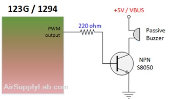
Figure 4: The Circuit for Music Player
In this lab, you will learn how to use PWM to generate DTMF tones. Now, based on what you've learned, you will design a MIDI player.
Download the NoteFreqsInt.zip file that provides frequencies of musical notes. Unzip the file into your project folder and include it in your project.
Create a new project with ezTivaLIB supported.
In your main.c file, you need to configure the system clock frequency:
- For TM4C123G board, use Setup_123G_20MHz() function to configure the system clock to 20 MHz.
- For TM4C1294 board, use Setup_1294_24MHz() function to configure the system clock to 24 MHz.
Configure a Right-Aligned PWM signal to drive the buzzer. The sound frequency ranges from 16 Hz to 20,000 Hz. Therefore, you have to select an appropriate PWMDIV value so that the PWM can generate all the sound signals.
In order to play MIDI music, you need to know its musical notes. Each note is played for a certain frequency and duration (delay), which is a certain time gap between two notes.
To play MIDI music, a sequence of PWM signals with the appropriate frequency must be generated. It means appropriate values have to be written to the LOAD register. PWM signal has to be generated as long as the note duration. When a short pause is required (note value equals zero), the PWM generation must be stopped for the appropriate period of time.
Steps to play a MIDI sound:
- Define a struct for the music. It includes tone and duration values.
typedef struct MELODY {
int note;
int duration;
} MELODY; - Define an array of the MELODY struct for the music.
- Create a function void PlayTone(uint16_t note, uint16_t duration)
- Disable the PWM generator.
- Convert note frequency to corresponding LOAD values, then write the value to the LOAD register.
- Setup CMP register to produce a 50% duty cycle
- Enable the PWM generator.
- Call a hardware timer delay for a duration time (using exTivaLIB)
- Disable the PWM generator
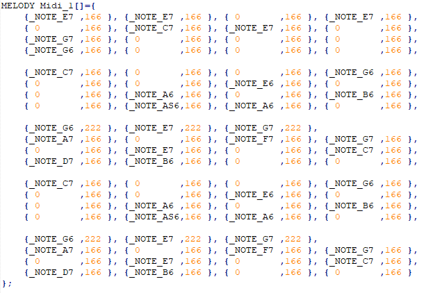
- Read the MIDI note and delay values from the Midi_1 structure array, then call the PlayTone() function to play the note. Continue to play all the notes in the Midi_1 array.
- Make a 1-second delay
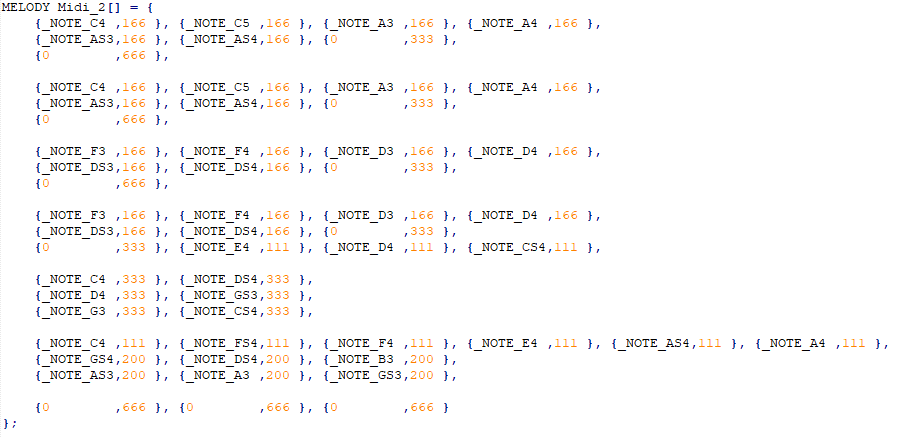
- Read the MIDI note and delay values from the Midi_2 structure array, then call the PlayTone() function to play the note. Continue to play all the notes in the Midi_2 array.
- Make another 1-second delay
- Jump to step 4, and repeat.
Add the the following two predefined MIDI arrays into your project:
MIDI Sound 1
MIDI Sound 2
Questions
- Can you recognize these two MIDI sounds? Where have you heard them before?
Questions
- What is the difference between active and passive buzzers?
- Can we use two PWMs that use the same PWM generator to generate the dial tone (for example, uses M0PWM2 and M0PWM3)? Explain why, or why not?