Lesson 13: Pulse-Width Modulation (PWM)
Pulse-Width Modulation (PWM)
Pulse-Width Modulation — What is it?
A good definition of Pulse-Width Modulation (PWM) is already in the name itself. It means modulating/varying the width of the pulse only, not the frequency. In the digital control system, PWM is used to control the amount of power sent to a device. Therefore, the PWM is a very effective technique for controlling analog devices using the digital outputs of a microcontroller. It is widely used in many fields, such as measurement, communication, power control, and transformation.
Principle
A PWM signal consists of two main components that define its behavior: a duty cycle and a frequency.
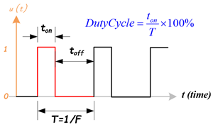
- Duty Cycle
The duty cycle describes the amount of time the signal is in a high (on) state as a percentage of the total time it takes to complete one cycle. A lower duty cycle corresponds to lower power because the power is off most of the time. The duty cycle is expressed percent, 100% duty cycle would be fully on as same as setting the signal to Vcc (high); 0% duty cycle would be the same as grounding the signal. - Frequency
The frequency determines how fast the PWM completes a cycle, ie. 100Hz would be 100 cycles per second. In other words, it shows how fast the PWM switches between high and low states.
In the digital system, PWM is the method to produce variable voltage using digital means. Typically, a digital system only has two output voltages, the high (5V, 3.3V … etc.) or the low (0V). But, how it is possible that a digital system can produce a voltage that is between the high and low voltages? Here, we use mathematics to analyze the PWM signal and the average output.
Mathematical Analysis of PWM signal
PWM uses a rectangular pulse wave whose pulse width is modulated resulting in the variation of the average value of the waveform. Consider a waveform such as shown in figure 2.
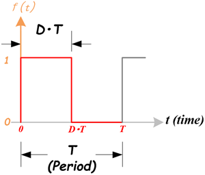 Figure 2: A Pulse Wave
The pulse signal is f(t) with period T and a duty cycle D (0.0~1.0). The average voltage of the waveform is given by:
\(\bar y = \frac{1}{T}\int_0^T {f(t)dt} \)
Just focus on one cycle T, as f(t) is a pulse wave, its positive-pulse is for 0 < t < D×T, and zero-pulse is for D×T < t < T. The above expression then becomes:
\(\begin{array}{l} \bar y = \frac{1}{T}\left( {\int_0^{DT} {1\;dt} + \int_{DT}^T {0\;dt} } \right)\\ \quad = \frac{1}{T}\left[ {DT \times 1 + T(1 - D) \times 0} \right]\\ \quad = D \end{array}\)
From this, it is obvious that the average value of the signal is directly dependent on the duty cycle D.
For example, if a digital signal produces a pulse high (5V) and a low (0V) equally, let us assume the signal in the high state for 1 microsecond and in a low state for 1 microsecond. The duty cycle is 50%, so the average voltage would be 2.5 volts. Now, change the high voltage in a high state for 7 microseconds and in a low state for 3 microseconds. The duty cycle now becomes to 70%, the average voltage would measure 70% of 5 volts or 5v x 0.7 = 3.5 volts.
Types of PWM
There are a couple of types of PWM, and they can be classified in different ways.
Classify PWM Signal by Methods: Symmetric and Asymmetric
There are two kinds of PWM signals: Symmetric and Asymmetric.
- Symmetric PWM:
- The pulses of asymmetric PWM signals are always symmetric with respect to the center of each PWM period.
- Symmetric PWM is often used for three-phase AC induction and brushless DC motors, due to the lower harmonic distortion that is generated on phase currents in comparison to asymmetric PWM methods.
- Asymmetric PWM:
- The pulses of an asymmetric PWM signal always have the same side aligned with one end of each PWM period.
- Asymmetric PWM can be used for stepper motors and other variable-reluctance motors.
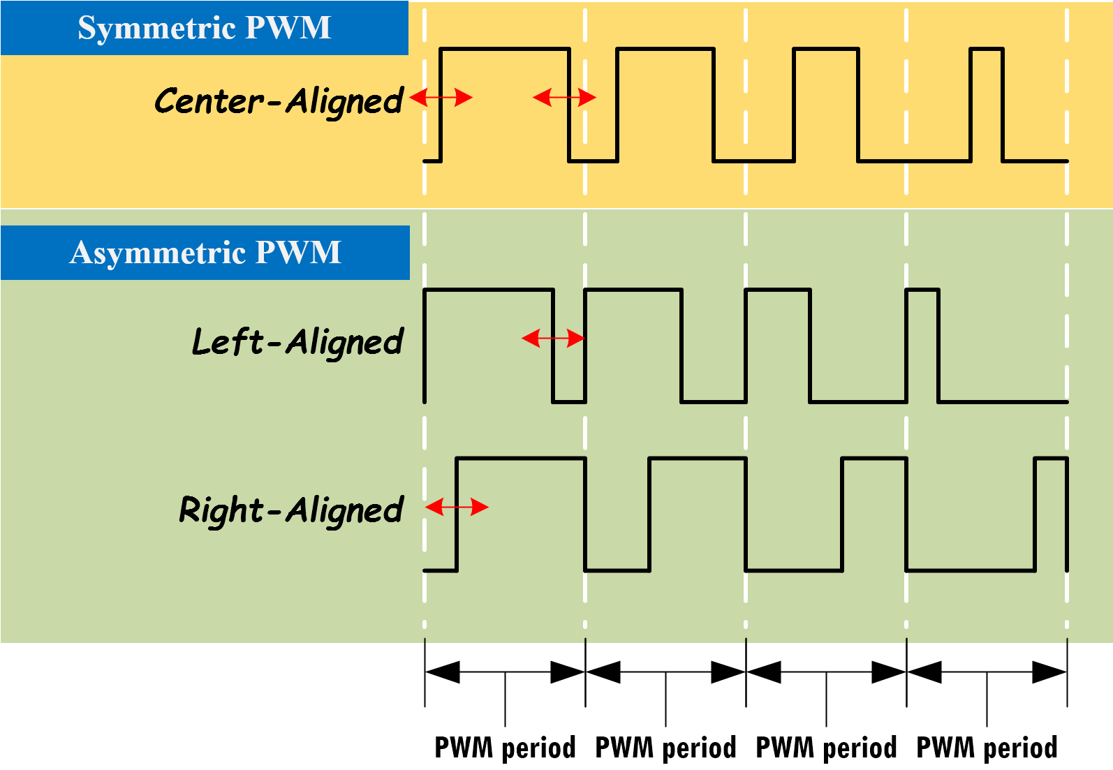
Figure 3: Three Types of PWM Signal: Center-Aligned, Left-Aligned, and Right-Aligned PWMs
Classify PWM Signal by Signal-Alignment
The PWM signal can be classified by signal alignment in four different types:
- Center-aligned PWM:
- Symmetric PWM
- Center-aligned PWMs are most often used in AC motor control to maintain phase alignment
- Left-aligned PWM
- Asymmetric PWM
- Left-aligned PWMs are used for most general-purpose PWM uses
- Right-aligned PWM
- Asymmetric PWM
- Right-aligned PWMs are typically only used in special cases that require alignment opposite of left-aligned PWMs
- Dual-edge PWM
- Dual-edged PWMs are optimized for power conversion where phase alignment must be adjusted
Generating PWM with Microcontroller using Timer/Counter
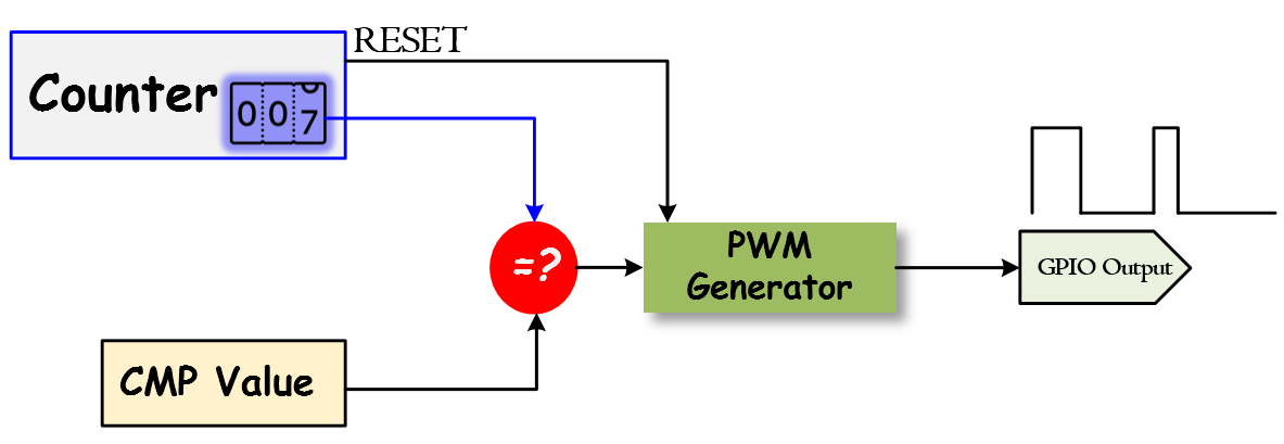
The basic idea to generate a PWM signal is to use a counter (or timer), a CMP (compare) value, and a digital output pin. The counter continuously counts up or down and is compared with the CMP value. The digital output (PWM) will be changed when the counter matches the CMP value, or when the counter resets. It can be implemented by software or hardware. Most microcontrollers already have hardware modules that can generate PWM signals after initializing the registers.
PWM Timer
The PWM timer in the microcontroller runs in one of two modes: Count-Down mode or Count-Up/Down mode.
- In Count-Down mode, the timer counts from the Period (LOAD) value to zero, goes back to the Period (LOAD) value, and continues counting down.
- In Count-Up/Dow mode, the timer counts from zero up to the Period (LOAD) value, back down to zero, back up to the Period (LOAD) value, and so on.
Generally, the Count-Down mode is used for generating left- or right-aligned PWM signals, while the Count-Up/Down mode is used for generating center-aligned PWM signals.
Check the microcontroller's datasheet about the PWM timer. Most of the ARM microcontrollers use Count-Down mode.
Center-Aligned PWM
Center-Aligned PWM
A center-aligned PWM implements the PWM differently from all of the other modes. The PWM timer is configured in counting-up and -down mode. The counter starts at zero and counts up to the Period (LOAD) value, and when the Period (LOAD) value is reached, the counter starts counting back down to zero. In this mode, the Period (LOAD) value is actually half of the period of the final PWM output.
- A single compare (CMP) value, which contains the duty cycle value, is constantly compared with the PWM timer (COUNTER) value. When the timer (COUNTER) value is less than the CMP value, the PWM output signal is de-asserted.
- When the timer (COUNTER) value exceeds or is equal to the CMP value, the PWM output signal is asserted. When the timer (COUNTER) value reaches the Period (LOAD) value, the timer starts counting down to zero.
- When the timer (COUNTER) value is less than or equal to the CMP value, the PWM output signal is de-asserted, and the process repeats.
Left-Aligned PWM
Left-Aligned PWM
To create the Left-Aligned PWM, a PWM timer counts down from a specified maximum value, called Period (LOAD) value, to zero. When the timer counts to zero, the Period (LOAD) value will be reloaded to the timer and continue to count down.
- When the timer (COUNTER) value is greater than the CMP value, the PWM output signal is asserted.
- When the timer (COUNTER) value is less than or equal to the CMP value, the PWM output signal is de-asserted.
- When the timer counts to zero, the timer will reload the value from the Period (LOAD) value.
Right-Aligned PWM
Right-Aligned PWM
To create the Right-Aligned PWM, the PWM timer still runs on counting-down mode
- When the timer (COUNTER) value is greater than the CMP value, the PWM output signal is de-asserted.
- When the timer (COUNTER) value is less than or equal to the CMP value, the PWM output signal is asserted.
- When the timer counts to zero, the timer will reload the value from the Period (LOAD) value, and the process repeats.
Dual-Edge PWM
Dual-Edge PWM
A dual-edge PWM uses two different aligned PWM, one is right-aligned and another is left-aligned. Those two PWMs are connected to an AND gate, the output is the dual-edge PWM signal.
PWM Module
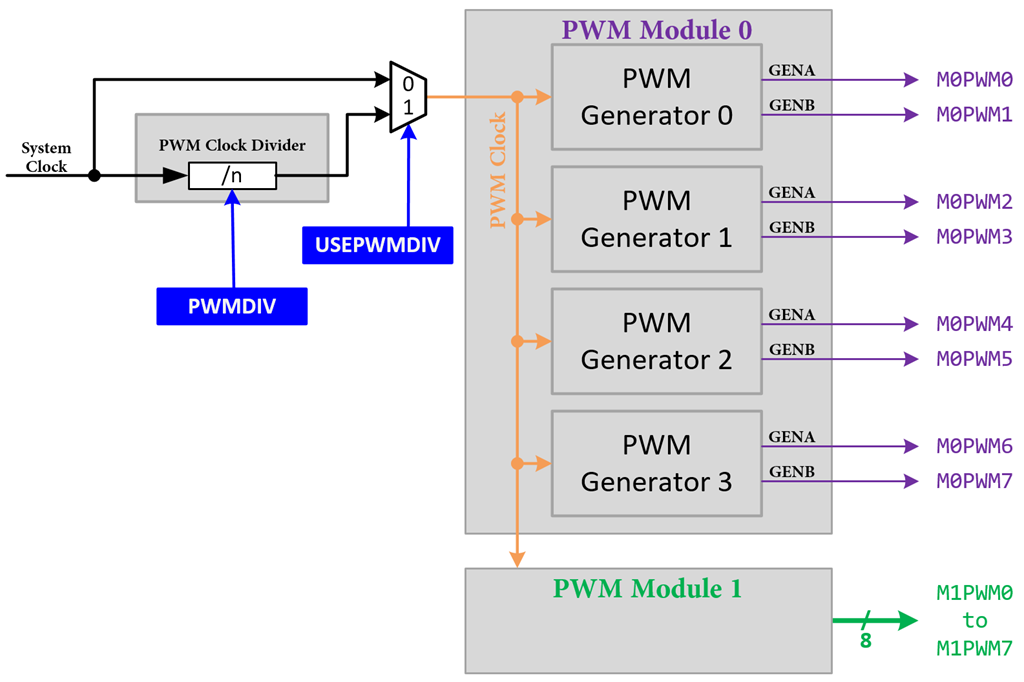
The PWM module in the TI TIVA microcontroller generates PWM signals. Each PWM module contains four PWM Generators. Each generator can produce two PWM signals. Therefore, one PWM module totally can generate eight PWM signals.
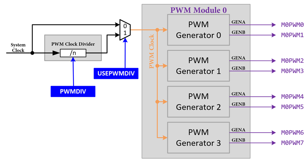
Figure 13.1: PWM Module Block Diagram
PWM Clock Configuration
The PWM module has two clock source options:
- The System Clock
- A pre divided System Clock
The clock source is selected by programming the USEPWMDIV bit in the Run-Mode Clock Configuration (RCC) register. The PWMDIV bit field specifies the divisor of the system clock that is used to create the PWM Clock.
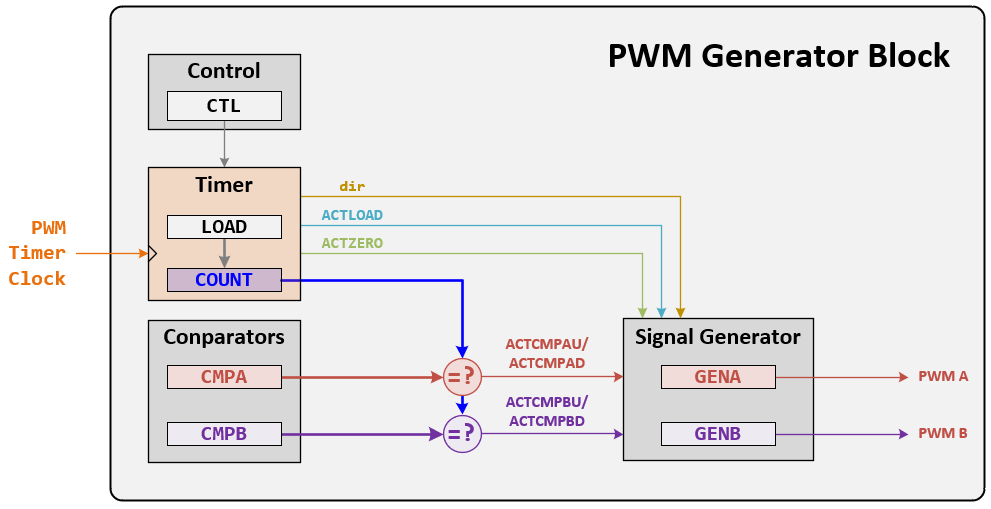
Figure 13.2: PWM Generator Block Diagram
PWM Timer
The timer in each PWM generator runs in one of two modes: Count-Down mode or Count-Up/Down mode.
- In Count-Down mode, the timer counts from the LOAD value to zero, then goes back to the LOAD value, and continues counting down.
- In Count-Up/Down mode, the timer counts from zero up to the LOAD value, back down to zero, then back up to the LOAD value, and so on.
Generally, the Count-Down mode is used for generating left- or right-aligned PWM signals, while the Count-Up/Down mode is used for generating center-aligned PWM signals
PWM Comparators
Each PWM generator has two comparators that monitor the value of the counter, when either comparator matches the counter, they output a single-clock-cycle-width High pulse, labeled "ACTCMPA" and "ACTCMPB" in Figure 13.2. When in Count-Up/Down mode, these comparators match both when counting up and when counting down, and thus are qualified by the counter direction signal. These qualified pulses are used in the PWM generation process. If either comparator match value is greater than the counter load value, then that comparator never outputs a High pulse.
The timers output three signals that are used in the PWM generation process: the direction signal (this is always Low in Count-Down mode, but alternates between low and high in Count-Up/Down mode), a single-clock-cycle-width High pulse when the counter is zero, and a single-clock-cycle-width High pulse when the counter is equal to the LOAD value. Note that in Count-Down mode, the zero pulse is immediately followed by the load pulse. In the figures in this chapter, these signals are labeled "dir", "ACTZERO", and "ACTLOAD".
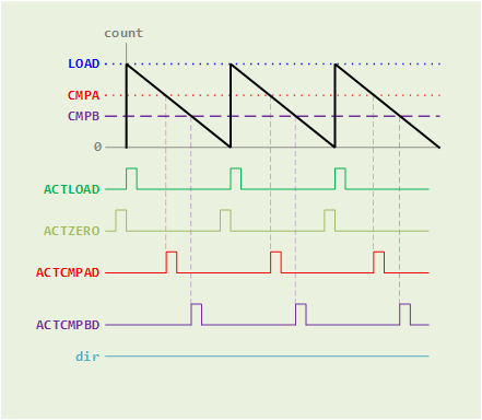
Figure 13.3 (a): PWM Count-Down Mode
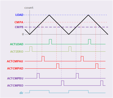
Figure 13.3 (b): PWM Count-UP/Down Mode
PWM Signal Generator
Each PWM generator takes the ACTLOAD, ACTZERO, ACTCMPAD, ACTCMPAU, ACTCMPBD, and ACTCMPBU pulses (qualified by the dir signal) and generates two internal PWM signals, GENA and GENB.
- In Count-Down mode, there are four events that can affect these signals: ACTZERO, ACTLOAD, ACTCMPAD (match CMPA down), and ACTCMPBD (match CMPB down).
- In Count-Up/Down mode, there are six events that can affect these signals: ACTZERO, ACTLOAD, ACTCOMAD (match CMPA down), ACTCMPAU (match CMPA up), ACTCMPBD (match CMPB down), and ACTCMPBU (match CMPB up). The match A or match B events are ignored when they coincide with the ACTZERO or ACTLOAD events. If the match CMPA and match CMPB events coincide, the first signal, GENA, is generated based only on the match CMPA event, and the second signal, GENB, is generated based only on the match CMPB event.
EK-TM4C123GXL LaunchPad
PWM Modules
The TM4C123GH6PM microcontroller contains two PWM modules, each module has four PWM generator blocks and a control block. Each PWM generator block produces two PWM signals, GENA and GENB. Both PWM output signals share the same PWM timer and frequency and can either be programmed with independent actions or as a single pair of complementary signals.
Each PWM generator block has the following features:
- One 16-bit counter
- Runs in Down or Up/Down mode
- PWM output frequency controlled by a 16-bit LOAD value
- Load value updates can be synchronized
- Produces output signals at zero and LOAD value
- Two PWM comparators (CMPA, CMPB)
- Comparator value updates can be synchronized
- Produces PWM output signals on match
- PWM signal generator
- Output PWM signal is constructed based on actions taken as a result of the counter and PWM comparator output signals
- Produces two independent PWM signals (GENA, GENB)
PWM I/Os
| PWM Output | GPIO Port.Pins (PMCn) | PWM | ||||
| Module (m) |
Generator (g) |
Single GEN | Output | |||
| M0PWM0 | PB6 (0x4) | 0 | 0 | GENA | PWM0 | |
| M0PWM1 | PB7 (0x4) | 0 | 0 | GENB | PWM1 | |
| M0PWM2 | PB4 (0x4) | 0 | 1 | GENA | PWM2 | |
| M0PWM3 | PB5 (0x4) | 0 | 1 | GENB | PWM3 | |
| M0PWM4 | PE4 (0x4) | 0 | 2 | GENA | PWM4 | |
| M0PWM5 | PE5 (0x4) | 0 | 2 | GENB | PWM5 | |
| M0PWM6 | PC4 (0x4) | PD0 (0x4) | 0 | 3 | GENA | PWM6 |
| M0PWM7 | PC5 (0x4) | PD1 (0x4) | 0 | 3 | GENB | PWM7 |
| M1PWM0 | PD0 (0x5) | 1 | 0 | GENA | PWM0 | |
| M1PWM1 | PD1 (0x5) | 1 | 0 | GENB | PWM1 | |
| M1PWM2 | PA6 (0x5) | PE4 (0x5) | 1 | 1 | GENA | PWM2 |
| M1PWM3 | PA7 (0x5) | PE5 (0x5) | 1 | 1 | GENB | PWM3 |
| M1PWM4 | PF0 (0x5) | 1 | 2 | GENA | PWM4 | |
| M1PWM5 | PF1 (0x5) | 1 | 2 | GENB | PWM5 | |
| M1PWM6 | PF2 (0x5) | 1 | 3 | GENA | PWM6 | |
| M1PWM7 | PF3 (0x5) | 1 | 3 | GENB | PWM7 | |
Registers
Assemble
The following steps show how to initialize PWM Generator
- Enable the clock signal for PWM module by setting its corresponding bit in the SYSCTL_RCGCPWM register, then waiting for PWM clock ready by checking the SYSCTL_PRPWM register
- Configure the Run-Mode Clock Configuration (SYSCTL_RCC) register to use the PWM divider (USEPWMDIV) and set the divider value (PWMDIV).
- Disable PWM generator by writing 0 to PWMnCTL[0] register
- Configure the PWM generator:
- Configure PWM signal by setting its corresponding bit in the PWMgGENA and/or PWMgGENB register
- Set the timer LOAD value to the PWMgLOAD register
- Set the pulse width value to the PWMgCMPA and/or PWMgCMPB registers
- Reset the PWM timer counter by resetting the PWM registers through the SRPWM register in the System Control Module
- Enable PWM generator by writing 1 to PWMgCTL[0] register
- Enable PWM output by setting its corresponding bit in the PWMENABLE register
After configuring the PWM, then you need to configure the GPIO pins that are connected to the PWM signal. The detailed information about GPIO configuration, please read Lesson 06: Loops.
- Enabled the clock signal to the GPIO Ports (SYSCTL_RCGCGPIO_R), then checking the ready signal (SYSCTL_PRGPIO)
- Unlock the port (GPIO_PORTn_LOCK_R). The step is needed only for PC[3:0], PD[7], and PF0 on TM4C123G. The only needing unlocking on the TM4C1294 is PD7. After unlocking the port, the appropriate bits of the GPIO Commit register (GPIO_PORTn_CR_R) need to be set.
- Disable the analog function of the pin (GPIO_PORTn_AMSEL_R)
- Configure bits in the port control register (GPIO_PORTn_PCTL_R) to select PWM function
- Configure bits in the Alternate Function Select register (GPIO_PORTn_AFSEL)
- Set the direction of the GPIO port pins (GPIO_PORTn_DIR_R)
- Program pull-up, pull-down, or open drain functionality (GPIO_PORTn_PUR_R , GPIO_PORTn_PDR_R , GPIO_PORTn_ODR_R)
- To enable GPIO pins (GPIO_PORTn_DEN_R)
C
The following steps show how to initialize PWM Generator:
- Enable the clock signal for PWM module by setting its corresponding bit in the SYSCTL->RCGCPWM register, then waiting for PWM clock ready by checking the SYSCTL->PRPWM register
- Configure the Run-Mode Clock Configuration (SYSCTL->RCC) register to use the PWM divider (USEPWMDIV) and set the divider value (PWMDIV).
- Disable PWM generator by writing 0 to PWMm->_g_CTL [0] register
- Configure the PWM generator:
- Configure PWM signal by setting its corresponding bit in the PWMm->_g_GENA and/or PWMm->_g_GENB register
- Set the timer LOAD value to the PWMm->_g_LOAD register
- Set the pulse width value to the PWMm->_g_CMPA and/or PWMm->_g_CMPB registers
- Reset PWM timer counter by resetting the PWM registers through the SRPWM register in the System Control Module
- Enable PWM generator by writing 1 to PWMm->_g_CTL [0] register
- Enable PWM output by setting its corresponding bit in the PWMm->ENABLE register
After configuring the PWM, then you need to configure the GPIO pins that are connected to the PWM signal. The detailed information about GPIO configuration, please read Lesson 06: Loops.
- Enabled the clock signal to the GPIO Ports (SYSCTL->RCGCGPIO |= (_PORTs);), then checking the ready signal (SYSCTL->PRGPIO)
- Unlock the port (GPIOn->LOCK). The step is needed only for PC[3:0], PD[7], and PF0 on TM4C123G. The only needing unlocking on the TM4C1294 is PD7. After unlocking the port, the appropriate bits of the GPIO Commit register (GPIOn->CR) need to be set.
- Disable the analog function of the pin (GPIOn->AMSEL)
- Configure bits in the port control register (GPIOn->PCTL) to select PWM function
- Configure bits in the Alternate Function Select register (GPIOn->AFSEL)
- Set the direction of the GPIO port pins (GPIOn->DIR)
- Program pull-up, pull-down, or open drain functionality (GPIOn->PUR, GPIOn->PDR, GPIOn->ODR)
- To enable GPIO pins (GPIOn->DEN)
The m is PWM Module number, g is the PWM Generator number, and n is the GPIO Port name.
Sample Firmware Code in Keil C
The following example code will configure the left-aligned PWM signal on PF1, which is connected with an onboard Red LED.
#include <stdio.h>
#include <stdlib.h>
#include <stdint.h>
#include <stdbool.h>

#include "TM4C123GH6PM.h"
// #include "MyDefines.h"  // Your Definition Header File

void Setup_PWM(void);
void Setup_GPIO(void);

int main()
{
    Setup_PWM();
    Setup_GPIO();

    while(1){
        // Place your application code here

    }
}
//------------------------------------------------------------------------------
void Setup_PWM(void)
{
    // 1. Enable Clock for PWM Modules
    SYSCTL->RCGCPWM |= 0x02;
    while((SYSCTL->PRPWM & 0x02) != 0x02 ){};
    // 2. Enable and Setup Clock Divider for PWM Timer
    SYSCTL->RCC |= (1 << 20);       // RCC[20]=1:USEPWMDIV
    SYSCTL->RCC &= ~(0x7 << 17);    // RCC[19:17]=000 PWMDIV
    SYSCTL->RCC |= (0x4 << 17);     // RCC[19:17]=0x4 divider=/32
    // 3. Disable PWM Generator and Setup the Timer Counting Mode
    PWM1->_2_CTL = 0x00;            // Disable PWM Generator, and set to count-down mode
    // 4. Configure LOAD (Period), CMP (Duty), GEN (PWM Mode) values
    PWM1->_2_LOAD = 50000;          // Setup the period of the PWM signal
    PWM1->_2_CMPB = 50000-2250;     // Setup the initial duty cycle
    PWM1->_2_GENB = (0x02 << 10 ) | (0x03 <<2); // ACTCMPBD=ActLow ACTLOAD=ActHigh
    // 5. Enable PWM Generator
    PWM1->_2_CTL |= 0x01;
    // 6. Enable PWM Output
    PWM1->ENABLE = (1 << 5);        // Enable PWM5
}
void Setup_GPIO(void)
{
    // GPIO Initialization and Configuration
    // 1. Enable Clock to the GPIO Modules (SYSCTL->RCGCGPIO |= (_PORTs);)
    SYSCTL->RCGCGPIO |= (_PORTs); |= ( );
    // allow time for clock to stabilize (SYSCTL->PRGPIO)
    while((SYSCTL->PRGPIO & (  )) != (  )){};

    // 2. Unlock GPIO only PD7, PF0 on TM4C123G; PD7, PE7 on TM4C1294 (GPIOx->LOCK = 0x4C4F434B; and GPIOx->CR = _PINs;)
    // 3. Set Analog Mode Select bits for each Port (GPIOx->AMSEL = _PINs; 0=digital, 1=analog)
    // 4. Set Port Control Register for each Port (GPIOx->PCTL = PMCn << _PTCL_PINn, check the PCTL table)
    // 5. Set Alternate Function Select bits for each Port (GPIOx->AFSEL = _PINs; 0=regular I/O, 1=PCTL peripheral)
    // 6. Set Output pins for each Port (Direction of the Pins: GPIOx->DIR = _PINs; 0=input, 1=output)
    // 7. Set PUR bits for internal pull-up, PDR for pull-down reg, ODR for open drain (0: disable, 1=enable)
    // 8. Set Digital ENable register on all GPIO pins (GPIOx->DEN = _PINs; 0=disable, 1=enable)
}
EK-TM4C1294XL LaunchPad
PWM Modules
The TM4C1294NCPDT microcontroller contains one PWM module, with four PWM generator blocks and a control block, for a total of 8 PWM outputs.
Each PWM generator block produces two PWM signals that share the same PWM timer and frequency and can either be programmed with independent actions or as a single pair of complementary signals. The output signals, GENA and GENB, of the PWM generation blocks are managed by the output control block before being passed to the device pins.
Each PWM generator block has the following features:
- One 16-bit counter
- Runs in Down or Up/Down mode
- PWM Output frequency controlled by a 16-bit LOAD value
- Load value updates can be synchronized
- Produces output signals at zero and load value
- Two PWM comparators (CMPA, CMPB)
- Comparator value updates can be synchronized
- Produces output signals on match
- PWM signal generator
- Output PWM signal is constructed based on actions taken as a result of the counter and PWM comparator output signals
- Produces two independent PWM signals
PWM I/O
| PWM Output | GPIO Port.Pins (PMCn) | PWM | ||||
| Module (m) |
Generator (g) |
Single GEN | Output | |||
| M0PWM0 | PF0 (0x6) | 0 | 0 | GENA | PWM0 | |
| M0PWM1 | PF1 (0x6) | 0 | 0 | GENB | PWM1 | |
| M0PWM2 | PF2 (0x6) | 0 | 1 | GENA | PWM2 | |
| M0PWM3 | PF3 (0x6) | 0 | 1 | GENB | PWM3 | |
| M0PWM4 | PG0 (0x6) | 0 | 2 | GENA | PWM4 | |
| M0PWM5 | PG1 (0x6) | 0 | 2 | GENB | PWM5 | |
| M0PWM6 | PK4 (0x6) | 0 | 3 | GENA | PWM6 | |
| M0PWM7 | PK5 (0x6) | 0 | 3 | GENB | PWM7 | |
Registers
The following steps show how to initialize PWM Generator
Assemble
- Enable the PWM clock by setting its corresponding bit in the SYSCTL_RCGCPWM register, then waiting for the PWM clock to ready by checking the SYSCTL_PRPWM register
- Configure the PWM Clock Configuration (PWMCC) register to use the PWM divide (USEPWMDIV) and set the divider (PWMDIV)
- Disable PWM generator by writing 0x00 to PWMgCTL register
- Configure the PWM generator:
- Configure PWM signal by setting its corresponding bit in the PWMgGENA and/or PWMgGENB register
- Set the timer LOAD value to the PWMgLOAD register
- Set the pulse width value to the PWMgCMPA and/or PWMgCMPB registers
- Reset the PWM timer counter by resetting the PWM registers through the SRPWM register in the System Control Module
- Enable PWM generator by writing 0x01 to PWMgCTL register
- Enable PWM Module by setting its corresponding bit in the PWMENABLE register
After configuring the PWM, then you need to configure the GPIO pins that are connected to the PWM signal. The detailed information about GPIO configuration, please read Lesson 06: Loops.
- Enabled the clock signal to the GPIO Ports (SYSCTL_RCGCGPIO_R), then checking the ready signal (SYSCTL_PRGPIO)
- Unlock the port (GPIO_PORTn_LOCK_R). The step is needed only for PC[3:0], PD[7], and PF0 on TM4C123G. The only needing unlocking on the TM4C1294 is PD7. After unlocking the port, the appropriate bits of the GPIO Commit register (GPIO_PORTn_CR_R) need to be set.
- Disable the analog function of the pin (GPIO_PORTn_AMSEL_R)
- Configure bits in the port control register (GPIO_PORTn_PCTL_R) to select PWM function
- Configure bits in the Alternate Function Select register (GPIO_PORTn_AFSEL)
- Set the direction of the GPIO port pins (GPIO_PORTn_DIR_R)
- Program pull-up, pull-down, or open drain functionality (GPIO_PORTn_PUR_R , GPIO_PORTn_PDR_R , GPIO_PORTn_ODR_R)
- To enable GPIO pins (GPIO_PORTn_DEN_R)
C
The following steps show how to initialize PWM Generator:
- Enable the clock signal for PWM module by setting its corresponding bit in the SYSCTL->RCGCPWM register, then waiting for PWM clock ready by checking the SYSCTL->PRPWM register
- Configure the Run-Mode Clock Configuration (PWMm->CC) register to use the PWM divider (USEPWMDIV) and set the divider value (PWMDIV).
- Disable PWM generator by writing 0 to PWMm->_g_CTL:[0] register
- Configure the PWM generator:
- Configure PWM signal by setting its corresponding bit in the PWMm->_g_GENA and/or PWMm->_g_GENB register
- Set the timer LOAD value to the PWMm->_g_LOAD register
- Set the pulse width value to the PWMm->_g_CMPA and/or PWMm->_g_CMPB registers
- Reset the PWM timer counter by resetting the PWM registers through the SRPWM register in the System Control Module
- Enable PWM generator by writing 1 to PWMm->_g_CTL:[0] register
- Enable PWM output by setting its corresponding bit in the PWMm->ENABLE register
After configuring the PWM, then you need to configure the GPIO pins that are connected to the PWM signal. The detailed information about GPIO configuration, please read Lesson 06: Loops.
- Enabled the clock signal to the GPIO Ports (SYSCTL->RCGCGPIO |= (_PORTs);), then checking the ready signal (SYSCTL->PRGPIO)
- Unlock the port (GPIOn->LOCK). The step is needed only for PC[3:0], PD[7], and PF0 on TM4C123G. The only needing unlocking on the TM4C1294 is PD7. After unlocking the port, the appropriate bits of the GPIO Commit register (GPIOn->CR ) need to be set.
- Disable the analog function of the pin (GPIOn->AMSEL)
- Configure bits in the port control register (GPIOn->PCTL) to select PWM function
- Configure bits in the Alternate Function Select register (GPIOn->AFSEL)
- Set the direction of the GPIO port pins (GPIOn->DIR)
- Program pull-up, pull-down, or open drain functionality (GPIOn->PUR, GPIOn->PDR, GPIOn->ODR)
- To enable GPIO pins (GPIOn->DEN)
The m is the PWM Module number, g is the PWM Generator number, and n is the GPIO Port name.
Sample Firmware Code in Keil C
The following example code will configure the left-aligned PWM signal on PF0, which is connected with an onboard Green LED.
#include <stdio.h>
#include <stdlib.h>
#include <stdint.h>
#include <stdbool.h>

#include "TM4C1294NCPDT.h"
// #include "MyDefines.h"  // Your Definition Header File

void Setup_PWM(void);
void Setup_GPIO(void);

int main()
{
    Setup_PWM();
    Setup_GPIO();

    while(1){
        // Place your application code here

    }
}
//------------------------------------------------------------------------------
void Setup_PWM(void)
{
    // 1. Enable Clock for PWM Module
    SYSCTL->RCGCPWM |= 0x01;
    while((SYSCTL->PRPWM & 0x01) != 0x01 ){};
    // 2. Enable and Setup Clock Divider for PWM Timer
    PWM0->CC  = (1 << 8);           // CC[8]:USEPWMDIV
    PWM0->CC &= ~0x7;               // CC[2:0]=000 PWMDIV
    PWM0->CC |= (0x2);              // CC[2:0]=0x2 divider = /8
    // 3. Disable PWM Generator and Setup the Timer counting mode
    PWM0->_0_CTL = 0x00;            // Disable PWM Generator, and set to count down mode
    // 4. Configure LOAD (Period), CMP (Duty), GEN (PWM Mode) values
    PWM0->_0_LOAD = 50000;          // Setup the period of the PWM signal
    PWM0->_0_CMPB = 50000-2250;     // Setup the initial duty cycle
    PWM0->_0_GENA = (0x02 << 6 ) | (0x03 <<2); // ACTCMPAD=ActLow ACTLOAD=ActHigh
    // 5. Enable PWM Generator
    PWM0->_0_CTL |= 0x01;           // Enable PWM Generator
    // 6. Enable PWM Output
    PWM0->ENABLE = 0x01;            // Enable PWM0
}
void Setup_GPIO(void)
{
    // GPIO Initialization and Configuration
    // 1. Enable Clock to the GPIO Modules (SYSCTL->RCGCGPIO |= (_PORTs);)
    SYSCTL->RCGCGPIO |= (_PORTs); |= ( );
    // allow time for clock to stabilize (SYSCTL->PRGPIO)
    while((SYSCTL->PRGPIO & (  )) != (  )){};

    // 2. Unlock GPIO only PD7, PF0 on TM4C123G; PD7, PE7 on TM4C1294 (GPIOx->LOCK = 0x4C4F434B; and GPIOx->CR = _PINs;)
    // 3. Set Analog Mode Select bits for each Port (GPIOx->AMSEL = _PINs;  0=digital, 1=analog)
    // 4. Set Port Control Register for each Port (GPIOx->PCTL = PMCn << _PTCL_PINn, check the PCTL table)
    // 5. Set Alternate Function Select bits for each Port (GPIOx->AFSEL = _PINs;  0=regular I/O, 1=PCTL peripheral)
    // 6. Set Output pins for each Port (Direction of the Pins: GPIOx->DIR = _PINs;  0=input, 1=output)
    // 7. Set PUR bits (internal Pull-Up Resistor), PDR (Pull-Down Resistor), ODR (Open Drain) for each Port (0: disable, 1=enable)
    // 8. Set Digital ENable register on all GPIO pins (GPIOx->DEN = _PINs; 0=disable, 1=enable)
}