Tiva Lab 06: Seven Segment Display
Objective
- Learn how to use a seven-segment display
- Learn how to use an array to store the predefined values
Required Reading Materials
Overview
In this lab, you will interface a seven-segment display to Tiva LaunchPad. The display counts from 0 ~ F and resets itself to zero. Before going further, let us first discuss seven-segment displays.
Seven Segment Display
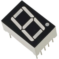
If your embedded system only needs to display numbers, you can consider using a seven-segment display. The seven-segment display is a simple device composed of 8 LEDs (the decimal point being the 8th). These LEDs can be lit in different combinations to represent Arabic numerals and some English characters.
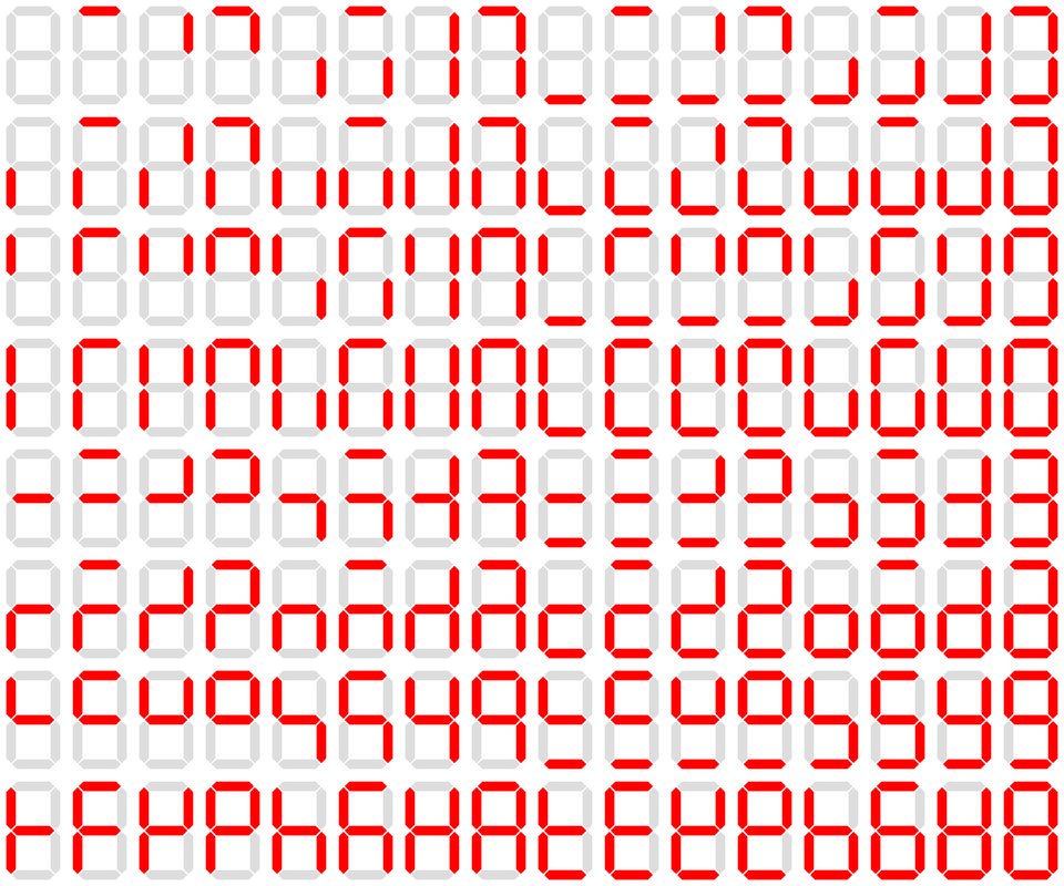
Figure 1: The 128 States of a Seven-Segment Display
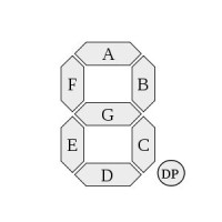
The segments of a seven-segment display are referred to by the letters A to G, with an optional decimal point (DP) for the display of non-integer numbers.
Types of Seven-Segment Displays
There are two main types of seven-segment displays available. In a simple LED package, as shown in the figure above, typically all of the cathodes (negative terminals) or all of the anodes (positive terminals) of the segment LEDs are connected and brought out to a common pin; this is referred to as a "common cathode" or a "common anode" device. Hence, a 7-segment plus decimal point package will only require nine pins, though commercial products typically contain more pins and/or places where pins would go to match standard IC sockets.
The Common Anode (CA)
In a common anode display, all the positive terminals (anodes) of the LED segments are connected together to logic "1" or Vcc on pins 3 and pin 8. To turn on an individual segment, you ground the corresponding pin through a current-limiting resistor to the cathode of that segment.
The Common Cathode (CC)
In a common cathode display, all the cathode connections of the LED segments are joined together to logic "0" or ground on pins 3 and pin 8. To use this type of display, you connect ground (GND) to pin 3 and/or pin 8 and apply a "HIGH" or logic "1" signal through a current-limiting resistor to the anode terminals.
Generally, common anode displays are more popular than common cathode displays since logic circuits can sink more current than they can source.
Displaying Numbers on a Seven-Segment Display
To display a number, you need to forward-bias the specific set of LEDs corresponding to the desired character.
To display the numerical digit "0," you must light up the LED segments corresponding to a, b, c, d, e, and f.
- Common Cathode: Connect these pins to power.
- Common Anode: Connect these pins to ground.
To display the numerical digit "1," you must light up the LED segments corresponding to b and c.
- Common Cathode: Connect these pins to power.
- Common Anode: Connect these pins to ground.
Displaying Letters and Hexadecimal Digits

Hexadecimal digits can also be displayed on a seven-segment display. A combination of uppercase and lowercase letters is used for letters 'A' to 'F' to ensure unique shapes for each hexadecimal digit. For example, a capital 'D' would look identical to a '0', and a capital 'B' would look identical to an '8' if not for this distinction. Additionally, the digit '6' must be displayed with the top bar lit to avoid ambiguity with the lowercase letter 'b'.
Displaying Letters on a Seven-Segment Display
Seven-segment displays can be used to show various letters from the Latin, Cyrillic, and Greek alphabets and punctuation. However, many representations are not both unambiguous and intuitive. Short messages conveying status information (e.g., "no disc" on a CD player ![]()
![]()
![]()
![]()
![]()
![]() ) are commonly shown on seven-segment displays. In these cases, each letter does not need to be clear as long as the overall message is readable.
) are commonly shown on seven-segment displays. In these cases, each letter does not need to be clear as long as the overall message is readable.
Below is a table illustrating how different letters can be displayed on a seven-segment display:
- A:

- b:

- C:
 c:
c: 
- d:

- E:

- F:

- G:

- H:
 h:
h: 
- I:

 i:
i: 


- J/j:


 j:
j: 
- L:
 l:
l: - n:

- O:
 o:
o: 
- P/p:

- q:

- r:

- S:

- t:

- U:
 u:
u: 
- Y/y:

- 0:
- 1:
- 2:

- 3:

- 4:

- 5:
- 6:

- 7:


- 8:

- 9:

- 10:
- 11:
- 12:
Encoding Methods for Seven-Segment Displays
A single byte can encode the full state of a seven-segment display. The most popular bit encodings is dpgfedcba and dpabcdefg, where each letter represents a particular segment in the display.
- 'dp.g.f.e.d.c.b.a' encoding: Encode segments a to g to bit 0 to bit 6, with the decimal point (dp) on bit 7.
- 'dp.a.b.c.d.e.f.g' encoding: Encode segments a to g to bit 6 to bit 7, with the decimal point (dp) on bit 7.
For example, in the dp.g.f.e.d.c.b.a encoding, a byte value of 0x06 would light up segments 'c' and 'b', displaying the number '1'.
Creating a Lookup Table for Hexadecimal Digits
A seven-segment display comprises 8 segments; we will label them a, b, c, d, e, f, g, and dp. This is the standard way to label each segment LED. Now, we need to make a lookup table to encode hexadecimal digits.
Here, we consider the decimal point (dp) pins are not used, so the dp values are always set to 0. We only consider segments a to f. Now we have to decide for every hex number (0 to F) and figure out what segments must be lit.
Example:
- Display '0':
- We want a, b, c, d, e, f on and g off.
- In the table, put '1' on segments a, b, c, d, e, f, and '0' on segment g.
- So, the output for the "dp.g.f.e.d.c.b.a" encoding is 0, 0, 1, 1, 1, 1, 1, 1. The binary value is 0b0011 1111 (or hex value 0x3F).
- Display '1':
- We want b and c on, and the rest of the segments are off.
- In the table, put '1' on segments b and c, and '0' on the rest of the segments.
- So, the output for the "dp.g.f.e.d.c.b.a" encoding is 0, 0, 0, 0, 0, 1, 1, 0. The binary value is 0b0000 0110 (or hex value 0x06)
Below is a lookup table for hexadecimal encoding using a common cathode seven-segment display. If using a common anode display, the values must be inverted. (Hover over each character with your mouse to see which segments need to be illuminated to display it.)
Table 1: Seven-Segment Display Lookup Table for Hexadecimal Encodings
| Digit | Display | Individual Segments Illuminated |
Port [7:0] | Port [7:0] | |||||||
| dp | g | f | e | d | c | b | a | dp.g.f.e.d.c.b.a | dp.a.b.c.d.e.f.g | ||
| 0 | |
0 | 0 | 1 | 1 | 1 | 1 | 1 | 1 | 0x3F | 0x7E |
| 1 | |
0 | 0 | 0 | 0 | 0 | 1 | 1 | 0 | 0x06 | 0x30 |
| 2 | |
||||||||||
| 3 | |
||||||||||
| 4 | |
||||||||||
| 5 | |
||||||||||
| 6 | |
||||||||||
| 7 | |
||||||||||
| 8 | |
||||||||||
| 9 | |
||||||||||
| A | |
||||||||||
| B | |
||||||||||
| C | |
||||||||||
| D | |
||||||||||
| E | |
||||||||||
| F | |
||||||||||
When connecting seven-segment displays in a circuit, a current limiting resistor must be wired in series with each display segment. Any resistor value between 100Ω and 1KΩ will work for the LED resistor. A lower resistance will result in a brighter segment. It is best to use resistors of the same value so all the segments light up evenly.
Components Required
 |
220 Ω Resistor | x 8 |
 |
7-Segment Display | x 1 |
| Breadboard | x 1 |
Circuit Diagram
The circuit diagram for connecting a common cathode seven-segment display to the TI Tiva microcontroller port is shown below. The microcontroller I/O pins source the current required for the segment LEDs. The current limiting resistors connected in series between the microcontroller pina and segment LEDs are 220ohm each. Segments a ~ g and dp are driven through GPIO output ports.
EK-TM4C123GXL LaunchPad
EK-TM4C123GXL LaunchPad
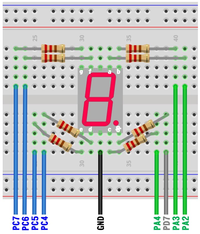
| dp | g | f | e | d | c | b | a | Pins on 7-Seg Display |
| 7 | 6 | 5 | 4 | 3 | 2 | 1 | 0 | Data bit |
| PD7 | PC7 | PC6 | PC5 | PC4 | PA4 | PA3 | PA2 | GPIO Port/Pin |
Pin configurations:
| Device | Port.Pin | Signal Type | PCTL | Direction | Drive Mode |
|---|---|---|---|---|---|
EK-TM4C1294XL LaunchPad
EK-TM4C1294XL LaunchPad
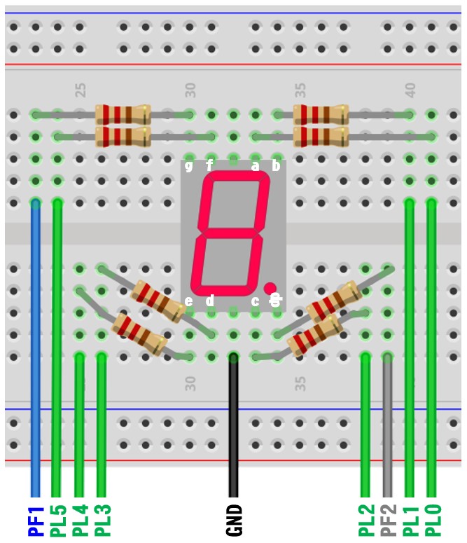
| dp | g | f | e | d | c | b | a | Pins on 7-Seg Display |
| 7 | 6 | 5 | 4 | 3 | 2 | 1 | 0 | Data bit |
| PF2 | PF1 | PL5 | PL4 | PL3 | PL2 | PL1 | PL0 | GPIO Port/Pin |
Pin configurations:
| Device | Port.Pin | Signal Type | PCTL | Direction | Drive Mode |
|---|---|---|---|---|---|
Procedures
- Create a new folder under the EE3450 folder and name it Lab06_7SegDisplay.
- Launch the Keil μVisio and create a new project. Save the project to the folder you created in the previous step and set the project name to Lab03_7SegDisplay.
- Add MyDefines.h to the Source Group, then add the Common folder to the include paths which is under the "Options for Target" setting.
GPIO Initialization and Configuration
GPIO Initialization Configuration
Next, we need to configure all the GPIO ports and pins that are used in the design.
According to the pin connections, complete the following GPIO configurations for each port. Fills the pin field by the value below:
- 0: Clean the bit
- 1: Set the bit
- x: Do not change the bit
- d: Do not care
For both TM4C123GXL and TM4C1294XL LaunchPads, the Port C [3:0] are used for JTAG/SWD. Therefore, when you configure Port C, you have to use bitwise operators to make sure your new configuration settings do not affect the JTAG/SWD function (PC3 ~ PC0).
Most of GPIO pins are configured as GPIOs and tri-stated by default (GPIOPCTL = 0, CPIOAFSEL = 0, GPIODIR = 0, GPIOPUR = 0, GPIOPDR = 0, GPIOODR = 0)
- Enable Clock to the GPIO Modules (RCGCGPIO register)
TM4C123G: SYSCTL->RCGCGPIO |= (_PORTs); |= binary = hex
8 4 2 1 8 4 2 1 7 6 5 4 3 2 1 0 bit Port F Port E Port D Port C Port B Port A port 0 0 -
TM4C1294: SYSCTL->RCGCGPIO |= (_PORTs); |= binary = hex
After enabling the clock signal, check the PRGPIO register until the corresponding bit is set to 1.8 4 2 1 8 4 2 1 8 4 2 1 8 4 2 1 15 14 13 12 11 10 9 8 7 6 5 4 3 2 1 0 bit Port Q Port P Port N Port M Port L Port K Port J Port H Port G Port F Port E Port D Port C Port B Port A port 0 - - -
In Assembly:
            LDR     R0, =SYSCTL_PRGPIO_R
Wait4GPIO   LDR     R1, [R0]
            TST     R1, #(__)
            BEQ     Wait4GPIO
In c:
while ( (SYSCTL->PRGPIO & ____ ) != ____ ) {}; - Unlock Port
TM4C123G: PD7 and PF0 are locked after reset.
TM4C1294: PD7 and PE7 are locked after reset
If those pins are used in the design, they must be unlocked first. To unlock the port, 0x4C4F434B must be written into the GPIOLOCK register and uncommit it by setting the GPIOCR register.
8 4 2 1 8 4 2 1 7 6 5 4 3 2 1 0 bit Port Pin 7 Pin 6 Pin 5 Pin 4 - Pin 3 Pin 2 Pin 1 Pin 0 pin Value in Hex Register Value to Register - - = ➤ GPIO ->LOCK = 0x4C4F434B - - = ➤ GPIO ->CR - - = ➤ GPIO ->LOCK = 0x4C4F434B - - = ➤ GPIO ->CR
Convert above configuration into registers
- GPIO Analog Mode Select
If any pin is used as an Analog signal (check Signal Type field on table 1), the appropriate bit in AMSEL must be set.
- 0: Digital signal
- 1: Analog signal
8 4 2 1 8 4 2 1 7 6 5 4 3 2 1 0 bit Port Pin 7 Pin 6 Pin 5 Pin 4 - Pin 3 Pin 2 Pin 1 Pin 0 pin Value in Hex Register Value to Register - - = ➤ GPIO ->AMSEL - - = ➤ GPIO ->AMSEL - - = ➤ GPIO ->AMSEL - - = ➤ GPIO ->AMSEL - - = ➤ GPIO ->AMSEL - - = ➤ GPIO ->AMSEL - - = ➤ GPIO ->AMSEL - GPIO Port Control (PCTL)
The PCTL register is used to select the specific peripheral signal for each GPIO pin when using the alternate function mode.
- 0: GPIO
- 1~0xF: Check the GPIO Pins and Alternate Function table
8421 8421 8421 8421 8421 8421 8421 8421 31~28 27~24 23~20 19~16 15~12 11~8 7~4 3~0 bit Port Pin 7 Pin 6 Pin 5 Pin 4 - Pin 3 Pin 2 Pin 1 Pin 0 pin Value in Hex Register Value to Register - - = ➤ GPIO ->PCTL - - = ➤ GPIO ->PCTL - - = ➤ GPIO ->PCTL - - = ➤ GPIO ->PCTL - - = ➤ GPIO ->PCTL - - = ➤ GPIO ->PCTL - - = ➤ GPIO ->PCTL - GPIO Alternate Function Select (AFSEL)
Setting a bit in the AFSEL register configures the corresponding GPIO pin to be controlled by PCTL peripheral function.
- 0: General I/O
- 1: Pin connected to the digital function defined in the PCTL register
8 4 2 1 8 4 2 1 7 6 5 4 3 2 1 0 bit Port Pin 7 Pin 6 Pin 5 Pin 4 - Pin 3 Pin 2 Pin 1 Pin 0 pin Value in Hex Register Value to Register - - = ➤ GPIO ->AFSEL - - = ➤ GPIO ->AFSEL - - = ➤ GPIO ->AFSEL - - = ➤ GPIO ->AFSEL - - = ➤ GPIO ->AFSEL - - = ➤ GPIO ->AFSEL - - = ➤ GPIO ->AFSEL - GPIO Pin Direction (DIR)
Set pin direction
- 0: Input pin
- 1: Output pin
8 4 2 1 8 4 2 1 7 6 5 4 3 2 1 0 bit Port Pin 7 Pin 6 Pin 5 Pin 4 - Pin 3 Pin 2 Pin 1 Pin 0 pin Value in Hex Register Value to Register - - = ➤ GPIO ->DIR - - = ➤ GPIO ->DIR - - = ➤ GPIO ->DIR - - = ➤ GPIO ->DIR - - = ➤ GPIO ->DIR - - = ➤ GPIO ->DIR - - = ➤ GPIO ->DIR - Internal Pull-Up Resistor (PUR), Pull-Down Resistor (PDR), and Open-Drain (ODR)
PUR: The pull-up control register
PDR: The pull-down control register
ODR: The open-drain control register
- 0: Disable
- 1: Enable
8 4 2 1 8 4 2 1 7 6 5 4 3 2 1 0 bit Port Pin 7 Pin 6 Pin 5 Pin 4 - Pin 3 Pin 2 Pin 1 Pin 0 pin Value in Hex Register Value to Register - - = ➤ GPIO -> - - = ➤ GPIO -> - - = ➤ GPIO -> - - = ➤ GPIO -> - - = ➤ GPIO -> - - = ➤ GPIO -> - - = ➤ GPIO -> - GPIO Digital Enable
Enables all the pins that are used in the design, including GPIO pins and alternate function pins.
- 0: Pin undriven
- 1: Enable pin
8 4 2 1 8 4 2 1 7 6 5 4 3 2 1 0 bit Port Pin 7 Pin 6 Pin 5 Pin 4 - Pin 3 Pin 2 Pin 1 Pin 0 pin Value in Hex Register Value to Register - - = ➤ GPIO ->DEN - - = ➤ GPIO ->DEN - - = ➤ GPIO ->DEN - - = ➤ GPIO ->DEN - - = ➤ GPIO ->DEN - - = ➤ GPIO ->DEN - - = ➤ GPIO ->DEN
Wire a circuit for the 7-segment display on the breadboard with eight current limiting resistors, then connect wires to the TI Tiva board. Make sure the power is disconnected when wiring up your breadboard.
The predefined hexadecimal encoding values must be shifted to the corresponding bit to light up the correct segment LED on different Ports.
Example Source Code
EK-TM4C123GXL LaunchPad
Since the PC0~PC3 are used for the JTAG interface when configuring GPIOC, the bitwise OR operation must be used to configure port C to avoid changing the configuration of PC0~PC3. For example:
GPIOC->DIR |= _PIN4 | _PIN5 | _PIN6 | _PIN7;
#include <stdio.h>
#include <stdlib.h>
#include <stdint.h>
#include <stdbool.h>

#include "TM4C123GH6PM.h"
#include "MyDefines.h"

void DelayMs(int ms);   // Software Delay Function
void SegDisplay(uint8_t d);
void Setup_GPIO(void);
// You nave to finish the following array for Seven Segment Display
char SevenSeg[] = { 0x3f,   // 0
                    0x06,   // 1
                            // You have to finish this array for 7-seg display
                  };

int main()
{
    char    ch = 0;
    int     i  = 0;
    // Place your initialization/startup code here (e.g. Setup_GPIO() )
    Setup_GPIO();

    while (1) {
        // Place your application code here
        for (i = 0; i < sizeof(SevenSeg); i++) {
            SegDisplay(ch & 0x0F);
            ch++;
            DelayMs(1000);
        }
    }
}
//------------------------------------------------------------------------------
void SegDisplay(uint8_t d)
{
    char    seg;

    seg = SevenSeg[?];

}
//------------------------------------------------------------------------------
/*
Device      Port.Pins       DIR     DriveMode
Seg-a
Seg-b
Seg-c
Seg-d
Seg-f
Seg-g
Seg-dp
SW1
SW2

Port ____
*/

void Setup_GPIO(void)
{
    // Configure GPIOs
    // 1. Enable Clock to the GPIO Modules (SYSCTL->RCGCGPIO |= (_PORTs);)
    SYSCTL->RCGCGPIO |= (__);
    // allow time for clock to stabilize (SYSCTL->PRGPIO & (_PORTs))
    while((SYSCTL->PRGPIO & (__)) != (__)) {};
    // 2. Unlock GPIO only PD7, PF0 on TM4C123G; PD7, PE7 on TM4C1294 (GPIOx->LOCK = 0x4C4F434B; and GPIOx->CR = _PINs;)
    GPIOD->LOCK = 0x4C4F434B;
    GPIOD->CR |= _PIN7;
    GPIOD->LOCK = 0;
    GPIOF->LOCK = 0x4C4F434B;
    GPIOF->CR |= _PIN0;
    GPIOF->LOCK = 0;
    // 3. Set Analog Mode Select bits for each Port (GPIOx->AMSEL = _PINs; 0=digital, 1=analog)
    // 4. Set Port Control Register for each Port (GPIOx->PCTL = PMCn << _PTCL_PINn, check the PCTL table)
    // 5. Set Alternate Function Select bits for each Port (GPIOx->AFSEL = _PINs; 0=regular I/O, 1=PCTL peripheral)
    // 6. Set Output pins for each Port (Direction of the Pins: GPIOx->DIR = _PINs; 0=input, 1=output)

    // 7. Set PUR bits (internal Pull-Up Resistor), PDR (Pull-Down Resistor), ODR (Open Drain) for each Port (0: disable, 1=enable)

    // 8. Set Digital ENable register on all port.pins (GPIOx->DEN = _PINs; 0=disable, 1=enable)

}
//------------------------------------------------------------------------------
// Delay ms milliseconds (16MHz CPU Clock)
void DelayMs(int ms)
{
    volatile int i, j;
    for (i = 0; i < ms; i++)
        for (j = 0; j < 4167; j++) {} // Do nothing for 1ms
}
EK-TM4C1294XL LaunchPad
#include <stdio.h>
#include <stdlib.h>
#include <stdint.h>
#include <stdbool.h>

#include "TM4C1294NCPDT.h"
#include "MyDefines.h"

void DelayMs(int ms);   // Software Delay Function
void SegDisplay(uint8_t d);
void Setup_GPIO(void);
// You nave to finish the following array for Seven Segment Display
char SevenSeg[] = { 0x3f,   // 0
                    0x06,   // 1
                            // You have to finish this array for 7-seg display
                  };

int main()
{
    char    ch = 0;
    int     i  = 0;
    // Place your initialization/startup code here (e.g. Setup_GPIO() )
    Setup_GPIO();

    while (1) {
        // Place your application code here
        for (i = 0; i < sizeof(sevenSeg); i++) {
            SegDisplay(ch & 0x0F);
            ch++;
            DelayMs(1000);
        }
    }
}
//------------------------------------------------------------------------------
void SegDisplay(uint8_t d)
{
    char    seg;

    seg = SevenSeg[?];

}
//------------------------------------------------------------------------------
/*
Device      Port.Pins       DIR     DriveMode
Seg-a
Seg-b
Seg-c
Seg-d
Seg-f
Seg-g
Seg-dp
SW1
SW2

Port ____
*/

void Setup_GPIO(void)
{
    // Configure GPIOs
    // 1. Enable Clock to the GPIO Modules (SYSCTL->RCGCGPIO |= (_PORTs);)
    SYSCTL->RCGCGPIO |= (__);
    // allow time for clock to stabilize (SYSCTL->PRGPIO & (_PORTs))
    while((SYSCTL->PRGPIO & (__)) != (__)){};
    // 2. Unlock GPIO only PD7, PF0 on TM4C123G; PD7, PE7 on TM4C1294 (GPIOx->LOCK = 0x4C4F434B; and GPIOx->CR = _PINs;)
    // 3. Set Analog Mode Select bits for each Port (GPIOx->AMSEL = _PINs; 0=digital, 1=analog)
    // 4. Set Port Control Register for each Port (GPIOx->PCTL = PMCn << _PTCL_PINn, check the PCTL table)
    // 5. Set Alternate Function Select bits for each Port (GPIOx->AFSEL = _PINs; 0=regular I/O, 1=PCTL peripheral)
    // 6. Set Output pins for each Port (Direction of the Pins: GPIOx->DIR = _PINs; 0=input, 1=output)

    // 7. Set PUR bits (internal Pull-Up Resistor), PDR (Pull-Down Resistor), ODR (Open Drain) for each Port (0: disable, 1=enable)

    // 8. Set Digital ENable register on all port.pins (GPIOx->DEN = _PINs; 0=disable, 1=enable)

}
//------------------------------------------------------------------------------
// Delay ms milliseconds (16MHz CPU Clock)
void DelayMs(int ms)
{
    volatile int i, j;
    for (i = 0; i < ms; i++)
        for (j = 0; j < 1605; j++) {} // Do nothing for 1ms
}
Lab Experiments
Comment out the for-loop code in the main function inside the while-loop.
    while (1) {
        // Place your application code here
//        for (i = 0; i < sizeof(sevenSeg); i++) {
//            SegDisplay(ch & 0x0F);
//            ch++;
//            DelayMs(1000);
//        }

    }
Exp #3.1: Pause/Resume the Counting
Write a C code to have your display count up from 0 to F (and then roll over to 0 again), with each digit displayed for one second.
- Modify your code, and add the onboard SW1 function to your project.
- After a power reset, the counter is STOP, and displays '0' on the 7-Segment Display.
- When the user presses SW1, the counter START to count up from 0 to F with a 1-sec interval and rolls over to 0 again.
- Users can press SW1 to PAUSE / CONTINUE the counter.
You can use software edge detection to implement the code:
The pseudocode for the Polling solution:
// Implement the following code inside the main() function
create bool variables: preSw1, curSw1, isPause
create integer variable: i, count
set preSw1 to true
set isPause to true
set i, count to zero
setup GPIO
display '0' on 7-seg display
loop
// 1. Read Current State
read current SW1 state to curSw1
// 2. Detect the falling edge
if (falling edge occurred)
invert isPause value
endif
// 3. Update preSw1 from curSw1
set preSw1 from curSw1
if isPause not true
increase count by 1
if count greater than 50
set count to zero
increase i value by 1
display i value on the 7-seg display
endif
endif
delay for 10 ms
repeat
Questions
- What type of seven-segment display did you use in this lab?
- Complete Table 1, which shows which segments must be illuminated to display the hex digits 0..F.
- If you used a common anode (CA) 7-segment display instead of a common cathode (CC) one, what change would you have to make in the wiring and the code?
- In this lab, we use eight resistors for each LED on a 7-segment display unit. Instead of using eight resistors, can you just use one 220 ohm resistor connected to the common ground of the unit, and have the equivalent circuit? Explain why or why not.