Project 001: Street Traffic Light
Level: ![]()
Objectives
- Understand the fundamentals of microcontroller programming and circuit design.
- Develop a basic traffic light control system with specified timings.
- Practice programming I/O interfaces on microcontrollers.
- Learn to debug and test embedded system projects.
Components Required
| Component/Device | Description | Quantity |
|---|---|---|
| 220 Ω (red red brn gld / red red blk blk brn) | × 6 | |
| Red LED | × 2 | |
| Green LED | × 2 | |
| Blue LED | × 2 |
Background
Traffic light systems manage the flow of traffic at intersections. By creating a model traffic light system, students can learn about sequential logic, timing control, and the basics of embedded system programming. This project involves creating a simplified version of a cross-road traffic management system using LEDs to represent traffic lights for the North-South and East-West directions.
Schematic Diagram
Utilize the following diagrams to set up the LEDs with the microcontroller.
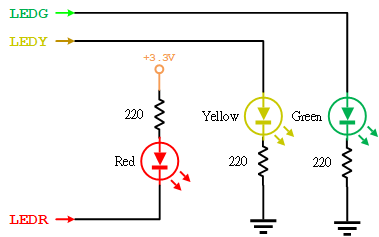
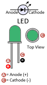
Figure 1: Schematic Diagram for Traffic Light
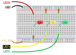
Figure 2: Connect the LEDs on the Breadboard
Pin Configuration Table
| Device | Port.Pin | Signal Type | Module | Direction | Drive Mode |
|---|---|---|---|---|---|
Crossroad Traffic Light System
For a complete simulation, construct two traffic lights:
- North-South Direction
- East-West Direction
Each light will follow the sequence:
- Green for 10 seconds
- Solid Yellow for 3 seconds
- Blinking Yellow for 2 seconds (500ms interval)
- Both directions turn red for a brief 1-second pause. Then, the cycle switches to another direction.
Lab Procedure
- Circuit Setup
- The green and yellow LED's anode (longer leg) connects to the digital output, and the cathode (shorter leg) goes to the ground (GND) through a resistor.
- The red LED's anode (longer leg) connects to the power source through a resistor, and the cathode (shorter leg) connects to the digital output pin.
- Arrange the LEDs in two sets (North-South and East-West), each comprising a Red, Yellow, and Green LED.
- Programming
- Initialize the pins connected to the LEDs as OUTPUT in your code's Setup_GPIO() function.
- Create a function for each traffic light sequence (Green, Solid Yellow, Blinking Yellow, Red).
- Implement the timing sequence using DelayMs() for the specified durations.
- Ensure that both directions turn red for a 1-second pause before switching to another direction.
- Use a loop to cycle through the sequence continuously.
- Testing and Debugging
- Upload the code to the microcontroller and observe the operation of the traffic light system.
- Check that the lights change according to the specified sequence and timings.
- If necessary, adjust the code or connections to correct any issues.
Did You Know? Relating to their first installation in London in 1868, traffic lights represent one of the foundational robotic systems impacting society. The three-colored pattern we recognize today was first seen in 1920.
Pseudocode
SETUP:
// Initialize digital pins connected to the LEDs as OUTPUT
Set all LED pins as OUTPUT
// Initial state: East-West direction is Red, all others OFF
Turn ON East-West Red LED
Turn OFF all other LEDs
LOOP:
// Cycle for North-South Direction (Green -> Yellow -> Blinking Yellow -> Red)
// East-West remains Red
Turn OFF North-South Red LED
Turn ON North-South Green LED for 10 seconds
Turn OFF North-South Green LED
Turn ON North-South Yellow LED for 3 seconds
Turn OFF North-South Yellow LED
// Blinking North-South Yellow LED sequence
FOR each cycle in 2 cycles DO
Turn ON North-South Yellow LED for 0.5 seconds
Turn OFF North-South Yellow LED for 0.5 seconds
Turn ON North-South Red LED
Delay for 1 second
// Prepare for East-West Direction cycle by setting North-South to Red
Turn ON North-South Red LED
// Cycle for East-West Direction (Green -> Yellow -> Blinking Yellow -> Red)
// North-South remains Red
Turn OFF East-West Red LED
Turn ON East-West Green LED for 10 seconds
Turn OFF East-West Green LED
Turn ON East-West Yellow LED for 3 seconds
Turn OFF East-West Yellow LED
// Blinking East-West Yellow LED sequence
FOR each cycle in 2 cycles DO
Turn ON East-West Yellow LED for 0.5 seconds
Turn OFF East-West Yellow LED for 0.5 seconds
Turn ON East-West Red LED
Delay for 1 second
REPEAT LOOP