
Project 003: LED Dice
Objective
- To design and program an electrical LED dice using a microcontroller and 7 LEDs
Design and write the program in the embedded system that generates a random number between 1 and 6 (inclusive) when a push button is pressed, and displays the corresponding number of dots on the 7 LEDs for 2 seconds. You can use a pseudo-random number generator and a switch-case statement to map the numbers to the LEDs. For example, 1 can be shown as the center dot, 2 as the opposite dots, 3 as a diagonal line, 4 as a square, 5 as a cross, and 6 as a hexagon. You may also add other features like sound, animation, or delay to enhance the user experience.
Components
- Microcontroller board (such as PSoC board, TI TIVA board, or similar)
- Breadboard and jumper wires
- 7 LEDs (2 yellows, 2 green LEDs, 2 blue LEDs, and one red LED)
- 11 220-ohm resistors
- An L293 TTL Chip (Datasheet)

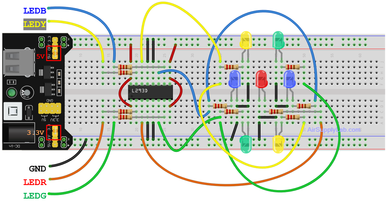
Circuit Diagram
- Insert the 7 LEDs on the breadboard to form a dice diagram, as shown above. Connect each LED to a 220-ohm resistor. The resistors limit the current flowing through the LEDs and protect them from damage due to overcurrent.
- Connect each LED-resistor pair to an output pin of the L293D chip as shown in the diagram.
- Connect pins LEDR, LEDG, LEDB, and LEDY to the microcontroller. Ensure that these pins are set to output mode in the program.
Safety Tips:
- Do not connect the LEDs directly to the digital pins without resistors.
- Disconnect the power cable (including the USB on the microcontroller board) before making any changes to the circuit.
Pin configurations
| Device | Port.Pin | Signal Type | Module | Direction | Drive Mode |
|---|---|---|---|---|---|
Procedure
- Start a new project in your IDE and create a folder named "003_LED_Dice".
- Include the necessary header files.
- Define the pins for 4 pairs of LEDs and a push button. Make sure that the pins for the LEDs are set to output mode, and the pin for the button is set to input mode with a pull-up resistor.
- Generate a random dice value and display it on the LEDs.
- If the push button (SW1) is pressed, continue to display a new random dice value every 200ms.
- If the button is released, continue to display a random dice value for 1 second, then stop.
- Check if the button is pressed again, and repeat steps 5 to 6 accordingly.
Programming Tips:
- To detect the state of SW1, consider using software edge detection methods that trigger an action when the button's state changes from pressed to released or vice versa. For example::
- When SW1 is pressed, start displaying new random dice values every 200 ms.
- When SW1 is released, continue to display new random dice values every 200ms for 1 second, then stop.