
Tiva Lab 11: Measure Pulse Width of PWM Signals using Timer
Objective
- To learn about timer input capture to measure period and pulse width
- To calculate the frequency and duty cycle
Required Reading Material
- Lesson 13: Pulse-Width Modulation (PWM)
- Lesson 18: Timer - Inputer Capture (Input Edge-Time) Mode
- EE3450-Tiva Lab 04: Interfacing Character LCD with Tiva LaunchPad
- Lesson 10: GPIO Port Control Register (GPIOPCTL)
- Lesson 09: GPIO Ports and Configurations
Background Information
The timer system in the TI Tiva microcontroller can be used for a variety of purposes. This lab will use the "Input Capture" ("Edge-Time") functionality, which is used to measure the length of a pulse. Timer input capture can be used for many features, such as:
- Measuring the width of a pulse
- Measuring the duty cycle of a signal
- Measuring the frequency of a signal
In this lab, you have to develop a code using the timer capture to measure the frequency and duty cycle values for several PWM signals and then display them on the LCD screen.
Fundamentals of Frequency Measurement
There are two methods of estimating the frequency of the square wave. The number of signal transitions (rising, falling, or both) in a fixed time interval can be counted, or the time interval between two consecutive signal transitions can be measured using a timer.
- For a high-frequency signal, measuring frequency by counting transitions over short intervals is more accurate for signals.
- Measuring the period is generally more precise fo relatively low-frequency signals. The resolution is provided by the number of timer counts between input signal transitions. For very low-frequency signals, may result in excessively long delays between measurement updates.
In this lab, you will learn how to use a timer to capture the rising and falling edges of a PWM signal, the difference between the capture values drives the pulse width time duration.
Required Components List
 |
Onboard Switch (SW1) | x 1 |
 |
Character LCD Module | x 1 |
 |
Onboard LED | x 1 |
Circuit Diagram
The following diagram shows the schematic of the design that uses the timer input capture to capture the rising and falling edges. The verification uses the PWM to generate the PWM signal — the input to the timer input capture pin.
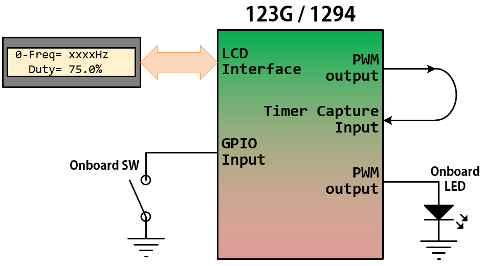
Procedure
Before the Lab, you must decide which ports and pins to use in this lab. Some pins are used to connect the LCD module, and one is an input pin for timer input capture; two are used to generate PWM output signals — one is connected to the Timer Input Capture pin, and the other is connected to the on-board LED. This lab will also use the onboard switch to change the PWM frequency and duty cycle.
Add EzTivaLIB to Your Project
The results will be shown on the LCD screen. Therefore, you have to include EzTivaLIB in your project. Please follow the article "Lesson 05: Branches" to add the library to your project.
The System Clock
A function Setup_123G_80MHz() or Setup_1294_80MHz() must be called at the beginning of the main() to configure the system clock to 80 MHz.
PWM signals
Develop a code that generates two PWM signals (both use the same PWM configuration):
- The frequency of the PWM timer is 10 MHz
- Generates Right-Aligned PWM signal
- The LOAD and CMP values have been defined in the template code
Timer Input Capture
Configure a general-purpose timer to operate as a 16-bit timer input capture mode with the pre-scale factor of 0xFF (255). This timer will be used to capture the time when the input signal transitions from low to high (rising edge), or high to low (falling edge).
Do not use the Timer5 (T5CCP0); it is used for the hardware timer delay functions — timer_waitMicros() and timer_waitMillis().
Write a C code that uses the Input Capture (Edge Time) feature of the Timer to find the period, then calculate the duty cycle and frequency of the PWM signal.
Period Measurement
Develop code to capture the main timer values corresponding to the period of one cycle:
- Configure the timer input capture event on the rising edge (or falling edge)
- Clean the bit of event status
- Capture the timer count value on the first rising edge (or falling edge)
- Clean the bit of event status
- Capture the timer counts value on the second edge (same edge as the first captured)
- Calculate the period counts value (T)
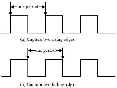
Figure 11-1: Period measurement by capturing two consecutive edges
Pulse Width Measurement
Develop code to capture the rising and falling edges
- Configure the timer input capture event on the rising edge
- Clean the bit of event status
- Capture the timer count value on the rising edge
- Configure the timer input capture event on the falling edge
- Clean the bit of event status
- Capture the timer count value on the falling edge
- Calculate the pulse with counter value (Δt)
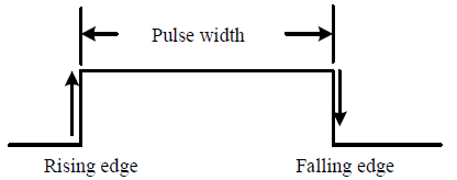
Figure 11-2: Pulse-width measurement using input capture
Duty Cycle Calculation
Then, you can get the value for the duty cycle and the frequency.
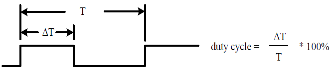
Figure 11-3: Definition of Duty Cycle
Configurations
Pin Configurations
| Device | Port.Pin | Signal Type | PCTL | Direction | Drive Mode |
|---|---|---|---|---|---|
PWM Connection and Configuration
PWM Initialization & Configuration
Find the frequency of the system clock, and calculate the frequency of the PWM Timer.
| System Clock SysClk (Hz) |
PWMDIV | fPWMTimer = SysClk / PWMDIV (Hz) |
Check the PCTL table (for 123G or 1294) to find the pins which support PWM peripheral signal
| GPIO Port.Pin |
PWM Module |
PCTL | PWM | |||||||
| Module (m) |
Generator (n) |
Signal GEN | Output | Signal Type | Output Frequency fPWM |
LOAD Value (16-bit) |
Initial CMP Value (16-bit) |
|||
You have to know the frequency of the System Clock (1), the frequency of PWM output signal (2), and the initial value for duty cycle (3). Then, calculate the LOAD value and CMP value.
\(LOA{D_{16bit}} = \frac{{{f_{PWMTimer}}}}{{{f_{PWM}}}}\)
For Left-Aligned PWM Signals
Calculate CMP value by duty cycle (%):
\(CM{P_{16bit}} = LOAD \times (1 - Dut{y_\% }) = \frac{{{f_{PWMTimer}}}}{{{f_{PWM}}}} \times (1 - Dut{y_\% })\)
Calculate CMP value by pulse width:
\(CM{P_{16bit}} = LOAD - \frac{{{T_{PulseWidth}}}}{{{T_{PWMTimer}}}} = ({T_{PWM}} - {T_{PulseWidth}}) \times {f_{PWMTimer}}\)
For Right-Aligned PWM Signals
Calculate CMP value by duty cycle (%):
\(CM{P_{16bit}} = LOAD \times Dut{y_\% } = \frac{{{f_{PWMTimer}}}}{{{f_{PWM}}}} \times Dut{y_\% }\)
Calculate CMP value by pulse width:
\(CM{P_{16bit}} = \frac{{{T_{PulseWidth}}}}{{{T_{PWMTimer}}}} = {T_{PulseWidth}} \times {f_{PWMTimer}}\)
The following steps show how to initialize PWM peripheral.
- Enable Clock to the PWM Modules (RCGCPWM register)
TM4C123G:
SYSCTL->RCGCPWM = MyDefines.h8 4 2 1 8 4 2 1 7 6 5 4 3 2 1 0 bit PWM
Module 1PWM
Module 0PWM 0 0 0 0 - 0 0
= binary = hex
TM4C1294:
SYSCTL->RCGCPWM = MyDefines.h8 4 2 1 8 4 2 1 7 6 5 4 3 2 1 0 bit PWM
Module 0PWM 0 0 0 0 - 0 0 0
= binary = hex
After enable clock signal, check the PRPWM register until the corresponding bit set to 1.
In C:
while ( (SYSCTL->PRPWM & (__) ) != (____ )) {}; - Enable and Setup Clock Divider for all PWM modules
USEPWMDIV: Enable PWM Clock Divisor
- 0: The system clock is the source for the PWM clock
- 1: The PWM clock divider is the source for the PWM clock
PWMDIV: PWM Unit Cloxk Divisor
- 0x0: /2
- 0x1: /4
- 0x2: /8
- 0x3: /16
- 0x4: /32
- 0x5: /64
TM4C123G:
SYSCTL->RCC &= ~(0x7 << 17); // RCC[19:17]=000 PWMDIVRCC 31 ~ 21 20 19 ~ 17 16 ~ 0 bit USEPWMDIV PWMDIV x x
SYSCTL->RCC |=
|= |=
TM4C1294:
PWM0->CC &= ~(0x7); // PWMCC[2:0]=000 PWMDIVPWMCC 31 ~ 9 8 7 ~ 3 2 ~ 0 bit USEPWMDIV PWMDIV x x
PWM0->CC |=
|= |= - PWM Signal Generation Control Register (PWMnCTL)
MODE: Counter Mode
- 0: Count-Down mode
- 1: Count-Up/Down mode
ENABLE: PWM Block Enable
- 0: The entire PWM generation block is disable and not not clocked
- 1: The PWM generation block is enabled and produces PWM signals
PWMnCTL 31 ~ 19 18 17 16 15 ~ 14 13 ~ 12 11 ~ 10 9 ~ 8 bit LATCH MINFLTPER FLTSRC DBFALLUPD DBRISEUPD DBCTLUPD GENBUPD x PWMnCTL 7 ~ 6 5 4 3 2 1 0 bit GENAUPD CMPBUPD CMPAUPD LOADUPD DEBUG MODE ENABLE PWM ->_ _CTL =
= = - Setup the Period of the PWM Signal (PWMnLOAD)
The 16-bit LOAD value is used to control the PWM period.
PWMnLOAD 31 ~ 16 15 ~ 0 bit LOAD PWM ->_ _LOAD =
- Setup the Initial Duty Cycle (PWMnCMPA / PWMnCMPB)
The PWMnCMPA / PWMnCMPB registers are used to compare against the PWM counter. When this value matches the counter, a pulse is output which can be configured to drive the pwmA and pwmB signals (via the PWMnGENA and PWMnGENB).
PWMnCMPA 31 ~ 16 15 ~ 0 bit CMPA PWM ->_ _CMPA =
PWMnCMPB 31 ~ 16 15 ~ 0 bit CMPB PWM ->_ _CMPB =
- Setup PWM Signal Type (PWMnGENA / PWMnGENB)
These register control the generation of the pwmA/pwmB signal based on the load and zero output pulses from the counter, as well as the compare A (CMPA) and compare B (CMPB) pulses from the comparators.
- 0x0: Do nothing
- 0x1: Invert PWM signal
- 0x2: Drive PWM signal Low
- 0x3: Drive PWM signal High
ACTCMPBD: Action for Comparator B in count-down mode
ACTCMPBU: Action for Comparator B in count-up mode
ACTCMPAD: Action for Comparator A in count-down mode
ACTCMPAU: Action for Comparator A in count-up mode
ACTLOAD: Action for Counter = LOAD
ACTZERO: Action for Counter = 0
Counter running in Count-Down mode
PWMnGENA/B 31 ~ 12 11 ~ 10 9 ~ 8 7 ~ 6 5 ~ 4 3 ~ 2 0 ~ 1 bit ACTCMPBD ACTCMPBU ACTCMPAD ACTCMPAU ACTLOAD ATZERO x PWM ->_ _GENA =
= =PWM ->_ _GENB =
= =
Counter running in Count-Up/Down mode
PWMnGENA/B 31 ~ 12 11 ~ 10 9 ~ 8 7 ~ 6 5 ~ 4 3 ~ 2 0 ~ 1 bit ACTCMPBD ACTCMPBU ACTCMPAD ACTCMPAU ACTLOAD ATZERO PWM ->_ _GENA =
= =PWM ->_ _GENB =
= = - PWM Output Enable (PWMnENABLE)
This register provides a master control of which PWM signals are output to the GPIO pins. By disabling a PWM output, the PWM generation process can continue without driving PWM signals to the pins.
- 0: The PWM signal has a zero value
- 1: The generated PWM signal is passed to the GPIO pin
8 4 2 1 8 4 2 1 7 6 5 4 3 2 1 0 bit PWM Module PWM
7PWM
6PWM
5PWM
4- PWM
3PWM
2PWM
1PWM
0pin Value in Hex Register Value to Register - - = ➤ PWM ->ENABLE - - = ➤ PWM ->ENABLE
GPIO Initialization and Configuration
GPIO Initialization Configuration
Next, we need to configure all the GPIO ports and pins that are used in the design.
According to the pin connections, complete the following GPIO configurations for each port. Fills the pin field by the value below:
- 0: Clean the bit
- 1: Set the bit
- x: Do not change the bit
- d: Do not care
For both TM4C123GXL and TM4C1294XL LaunchPads, the Port C [3:0] are used for JTAG/SWD. Therefore, when you configure Port C, you have to use bitwise operators to make sure your new configuration settings do not affect the JTAG/SWD function (PC3 ~ PC0).
Most of GPIO pins are configured as GPIOs and tri-stated by default (GPIOPCTL = 0, CPIOAFSEL = 0, GPIODIR = 0, GPIOPUR = 0, GPIOPDR = 0, GPIOODR = 0)
- Enable Clock to the GPIO Modules (RCGCGPIO register)
TM4C123G: SYSCTL->RCGCGPIO |= (_PORTs); |= binary = hex
8 4 2 1 8 4 2 1 7 6 5 4 3 2 1 0 bit Port F Port E Port D Port C Port B Port A port 0 0 -
TM4C1294: SYSCTL->RCGCGPIO |= (_PORTs); |= binary = hex
After enabling the clock signal, check the PRGPIO register until the corresponding bit is set to 1.8 4 2 1 8 4 2 1 8 4 2 1 8 4 2 1 15 14 13 12 11 10 9 8 7 6 5 4 3 2 1 0 bit Port Q Port P Port N Port M Port L Port K Port J Port H Port G Port F Port E Port D Port C Port B Port A port 0 - - -
In Assembly:
            LDR     R0, =SYSCTL_PRGPIO_R
Wait4GPIO   LDR     R1, [R0]
            TST     R1, #(__)
            BEQ     Wait4GPIO
In c:
while ( (SYSCTL->PRGPIO & ____ ) != ____ ) {}; - Unlock Port
TM4C123G: PD7 and PF0 are locked after reset.
TM4C1294: PD7 and PE7 are locked after reset
If those pins are used in the design, they must be unlocked first. To unlock the port, 0x4C4F434B must be written into the GPIOLOCK register and uncommit it by setting the GPIOCR register.
8 4 2 1 8 4 2 1 7 6 5 4 3 2 1 0 bit Port Pin 7 Pin 6 Pin 5 Pin 4 - Pin 3 Pin 2 Pin 1 Pin 0 pin Value in Hex Register Value to Register - - = ➤ GPIO ->LOCK = 0x4C4F434B - - = ➤ GPIO ->CR - - = ➤ GPIO ->LOCK = 0x4C4F434B - - = ➤ GPIO ->CR
Convert above configuration into registers
- GPIO Analog Mode Select
If any pin is used as an Analog signal (check Signal Type field on table 1), the appropriate bit in AMSEL must be set.
- 0: Digital signal
- 1: Analog signal
8 4 2 1 8 4 2 1 7 6 5 4 3 2 1 0 bit Port Pin 7 Pin 6 Pin 5 Pin 4 - Pin 3 Pin 2 Pin 1 Pin 0 pin Value in Hex Register Value to Register - - = ➤ GPIO ->AMSEL - - = ➤ GPIO ->AMSEL - - = ➤ GPIO ->AMSEL - - = ➤ GPIO ->AMSEL - - = ➤ GPIO ->AMSEL - - = ➤ GPIO ->AMSEL - - = ➤ GPIO ->AMSEL - GPIO Port Control (PCTL)
The PCTL register is used to select the specific peripheral signal for each GPIO pin when using the alternate function mode.
- 0: GPIO
- 1~0xF: Check the GPIO Pins and Alternate Function table
8421 8421 8421 8421 8421 8421 8421 8421 31~28 27~24 23~20 19~16 15~12 11~8 7~4 3~0 bit Port Pin 7 Pin 6 Pin 5 Pin 4 - Pin 3 Pin 2 Pin 1 Pin 0 pin Value in Hex Register Value to Register - - = ➤ GPIO ->PCTL - - = ➤ GPIO ->PCTL - - = ➤ GPIO ->PCTL - - = ➤ GPIO ->PCTL - - = ➤ GPIO ->PCTL - - = ➤ GPIO ->PCTL - - = ➤ GPIO ->PCTL - GPIO Alternate Function Select (AFSEL)
Setting a bit in the AFSEL register configures the corresponding GPIO pin to be controlled by PCTL peripheral function.
- 0: General I/O
- 1: Pin connected to the digital function defined in the PCTL register
8 4 2 1 8 4 2 1 7 6 5 4 3 2 1 0 bit Port Pin 7 Pin 6 Pin 5 Pin 4 - Pin 3 Pin 2 Pin 1 Pin 0 pin Value in Hex Register Value to Register - - = ➤ GPIO ->AFSEL - - = ➤ GPIO ->AFSEL - - = ➤ GPIO ->AFSEL - - = ➤ GPIO ->AFSEL - - = ➤ GPIO ->AFSEL - - = ➤ GPIO ->AFSEL - - = ➤ GPIO ->AFSEL - GPIO Pin Direction (DIR)
Set pin direction
- 0: Input pin
- 1: Output pin
8 4 2 1 8 4 2 1 7 6 5 4 3 2 1 0 bit Port Pin 7 Pin 6 Pin 5 Pin 4 - Pin 3 Pin 2 Pin 1 Pin 0 pin Value in Hex Register Value to Register - - = ➤ GPIO ->DIR - - = ➤ GPIO ->DIR - - = ➤ GPIO ->DIR - - = ➤ GPIO ->DIR - - = ➤ GPIO ->DIR - - = ➤ GPIO ->DIR - - = ➤ GPIO ->DIR - Internal Pull-Up Resistor (PUR), Pull-Down Resistor (PDR), and Open-Drain (ODR)
PUR: The pull-up control register
PDR: The pull-down control register
ODR: The open-drain control register
- 0: Disable
- 1: Enable
8 4 2 1 8 4 2 1 7 6 5 4 3 2 1 0 bit Port Pin 7 Pin 6 Pin 5 Pin 4 - Pin 3 Pin 2 Pin 1 Pin 0 pin Value in Hex Register Value to Register - - = ➤ GPIO -> - - = ➤ GPIO -> - - = ➤ GPIO -> - - = ➤ GPIO -> - - = ➤ GPIO -> - - = ➤ GPIO -> - - = ➤ GPIO -> - GPIO Digital Enable
Enables all the pins that are used in the design, including GPIO pins and alternate function pins.
- 0: Pin undriven
- 1: Enable pin
8 4 2 1 8 4 2 1 7 6 5 4 3 2 1 0 bit Port Pin 7 Pin 6 Pin 5 Pin 4 - Pin 3 Pin 2 Pin 1 Pin 0 pin Value in Hex Register Value to Register - - = ➤ GPIO ->DEN - - = ➤ GPIO ->DEN - - = ➤ GPIO ->DEN - - = ➤ GPIO ->DEN - - = ➤ GPIO ->DEN - - = ➤ GPIO ->DEN - - = ➤ GPIO ->DEN
- Connect a wire from the PWM output pin to the timer input capture pin.
- Start a new project (or re-use the project from the previous parts), and load the template code from the CSULA Canvas website.
- Fill in the configuration tables above. Then, according to the configuration tables, use the register settings for PWM, Timer, and GPIO ports.
Lab Experiment
Experiment 1:
Fill in the table below with the results from the calculation and the LCD screen displayed: (The output signals are Right-Aligned PWM)
- Calculates the PWM output frequency and duty cycle values.
- Download your code to the Tiva LaunchPad, and press the "RESET" button to start your code.
- The LCD screen will show the signal frequency and duty cycle through the timer input capture. Record the values in the table.
- Press and hold the onboard switch (for 1 sec) to re-configure the PWM signal, and then repeat steps 3 and 4 for each PWM signal.
Table 1: The Measurement Result
| PWM Signal Output | The Results are shown on the LCD Screen | |||||
| LOAD Value | CMP Value | Frequency (Hz) = (10M / LOAD) |
Duty (%) = (CMP / LOAD) x 100%) |
Frequency (Hz) | Duty (%) | |
| 0 | 18150 | 4628 | ||||
| 1 | 6665 | 3032 | ||||
| 2 | 12490 | 8118 | ||||
| 3 | 49996 | 37497 | ||||
| 4 | 8328 | 2914 | ||||
Questions
- Complete Table 1, which shows the results from the experiments and calculations.
- Compare your results with the values you calculated in Table 1. Calculate the percent error for each PWM signal's frequency and duty cycle values.
\(\% error = \left| {\frac{{({\rm{actual value}}) - ({\rm{experimental value}})}}{{{\rm{actual value}}}}} \right| \times 100\% \) - Can we configure the timer input capture event on both edges mode to measure the pulse width of the input PWM signal? Please explain why or why not.
- Briefly describe the "Input Capture" function.
- How often will the 16-bit timer roll over if it uses the default system clock of 16MHz and a Prescaler factor of 0x0F?
- What register is used to select the type of events that will trigger a TimerA Input Capture?
- What register stores the current counter value for Timer A?
Exercises
Ex1: Edge-Count to Measure the Frequency of PWM signals
Develop an embedded system program that utilizes the Edge Count and Periodic modes of the Timer to count rising or falling edges in a PWM signal pulse train for a duration of 10 seconds. Employ an additional pin connected to the onboard LED. Initially, at t = 0, activate the LED and enable the Edge Count system to track rising or falling edges in the PWM signal pulse train. Once t = 10 seconds is reached, disable the LED and cease counting the specified edges. Upon completion, display the counter value on the LCD screen. Press the onboard switch to initiate a new counting cycle and modify the PWM signal.
Question:
- Is it possible to generate a square wave (50% duty cycle) over a period of 10 hours using the Periodic mode of the 16-bit Timer? If yes, explain how, and if no, explain why not. You do not need to write a program or flow chart to justify your answer.
Submit your completed project report, including your working code.